Removal
1. Remove the steering column from the vehicle as described in previous Section, then clamp the column in a vice with soft protective jaws.
2. If you have not already done so, remove the steering wheel from the column as described in Section 22.
3. Remove the driver cartridge, then, by hooking it, release the clamp. Pull out the spring and the upper thrust washer (see Figure 24.3).
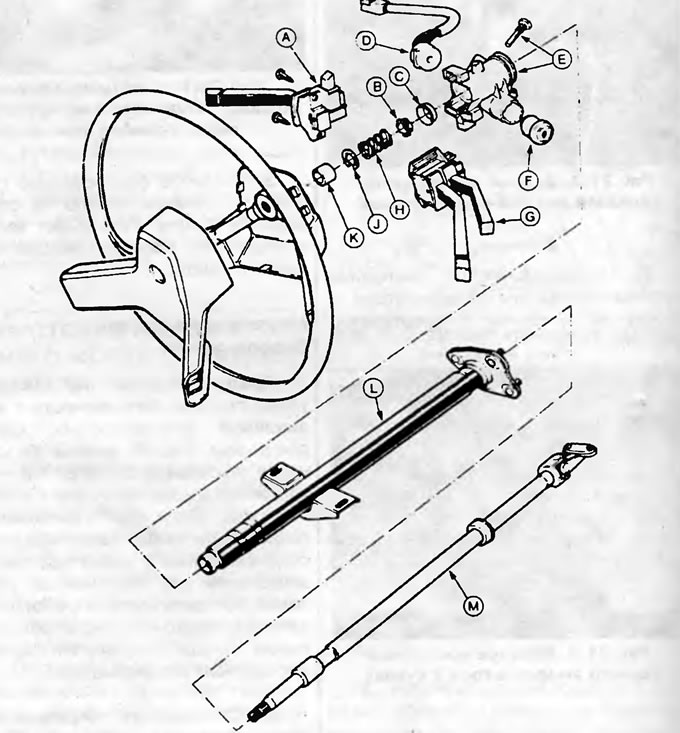
Figure 24.3. Detailed view of the steering column: A - Left multifunction switch; B - Thrust washer; C - Thrust bearing; D - Wiring harness; E - Ignition switch; F - Ignition lock cylinder; G - Right multifunction switch; H - Spring; J - Snap ring; K - Driver cartridge; L - Steering column pipe; M - Steering column shaft.
4. Insert the ignition key into the lock and turn it to position "II". The steering column shaft can now be removed.
5. Loosen the screws securing the column's multi-function switches and remove the switches.
6. To remove the steering column lock, drill out the shear bolt securing the lock to the column with a 3/16 in diameter drill bit, then carefully knock the lock outward (see Figure 24.6).
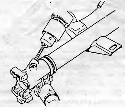
Figure 24.6. To remove the steering column lock, drill out the shear bolt securing the lock to the column.
7. To remove the upper column support bearing, pry it up and push it out.
8. Remove the two headless (slotted) screws to separate the wiring harness plate from the ignition switch housing.
9. To remove the ignition lock cylinder, turn the ignition key to position "I". Then insert a thin punch into the hole in the lock housing and push the lock cylinder out (see Figure 24.9).
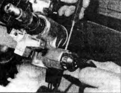
Figure 24.9. Removing the ignition lock cylinder.
Inspection
10. Carefully inspect the condition of the steering column and its shaft, paying attention to any signs of deformation or distortion.
11. Check for play, which indicates excessive wear on the universal joint.
12. Check that there is no excessive play in the steering shaft in the column tube, indicating wear of the upper bracket bearing.
13. Replace all defective or obviously worn components with new ones. If the column is damaged, replace it with a new one.
Assembly
14. First, install the lock cylinder. With the ignition key in position "I", insert the lock cylinder into the crankcase and push it in until it stops and you feel the lock pin engage with the column lock bushing.
15. Turn the ignition key to position "0", then install the wire harness plate, securing it with two headless screws.
16. Place the lock housing onto the steering column pipe until it stops. Screw in a new shear bolt and tighten it until the bolt head breaks.
17. Install the upper steering shaft thrust bearing onto the outer tube.
18. Turn the ignition key to position "II", place the assembled part of the column on the pipe, install the lower bearing and the upper thrust washer with the spring.
19. With the shaped washer positioned on the shaft, install the shaft onto the column using a suitable tubular punch to secure the spring. Replace the driver cartridge.
20. After installing the multi-function switches, install the column and steering wheel as described in the previous Sections.
21. Upon completion, check the operation of the multifunction switches on the steering column and the ignition switch.