Removal
1. Disconnect the negative battery cable.
2. Position the steering wheel so that the wheels point straight ahead and lock the column in this position.
3. Unscrew the bolt of the ball joint pressure plate connecting the steering column to the universal joint. Move the pressure plate to the side. Please note that a new bolt will be required when installing the pressure plate.
4. After loosening the front wheel bolts, jack up the front of the car and place it on supports. Remove the front wheels.
5. Referring to Section 26, disconnect the tie rod end ball joints from the steering arms.
6. After removing the bolts securing the steering gear to the crossmember, move the steering gear downward to disconnect the universal joint from the steering column.
7. Unscrew the clamping bolt and separate the cardan joint from the pinion shaft.
8. To remove the mounting bushings, they must be pressed out or knocked out using a pipe or socket of a suitable diameter.
Disassembly
9. Secure the steering gear in a vice with protective pads on the cheeks. Cut the retaining clips of the protective covers ("accordions") of the steering gear and remove the "accordions" down the transverse steering rod. Remove the protective cap of the gear (see Figure 25.9).
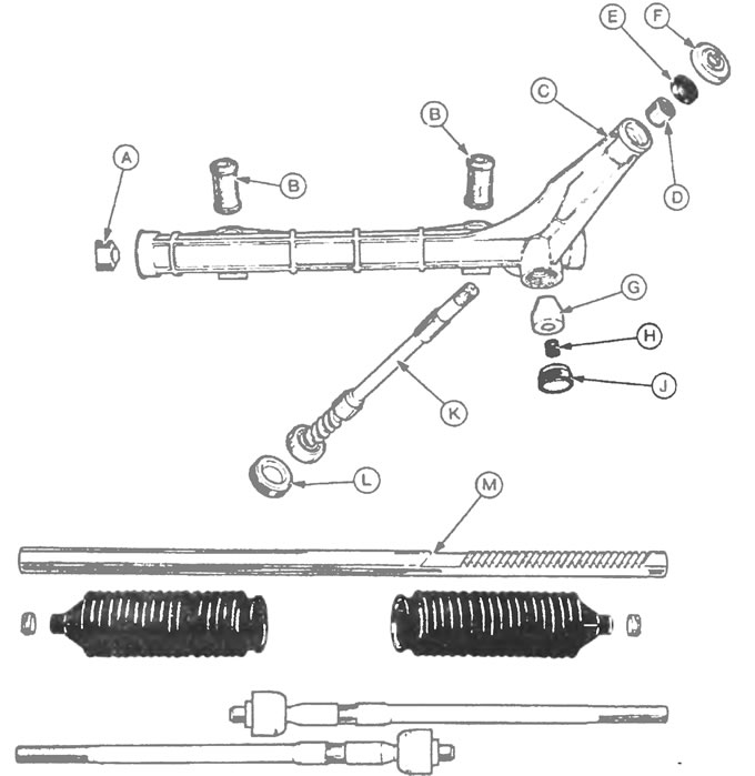
Figure 25.9. Rack and pinion steering mechanism: A - Rack guide bushing, B - Mounting bushings, C - Steering gear housing, D - Upper pinion bearing, E - Upper seal, F - Protective cap, G - Rack stop, H - Spring, J - Rack stop nut, K - Steering gear pinion, L - Pinion bearing cover, M - Steering rack.
10. Move the steering rack completely to the left (on right-hand drive models) or, accordingly, to the right (on left-hand drive models), hold her in a vice with soft pads on her cheeks.
11. If the vehicle is equipped with the original tie rods, unscrew the ball joint from the toothed rack with a pipe wrench and remove the left tie rod (see Figure 25.11). If the tie rods have been replaced in the past, use a wrench placed on the flats.
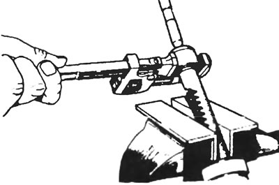
Figure 25.11. If the vehicle is equipped with original tie rods, unscrew the ball joint from the toothed rack using a pipe wrench and remove the left tie rod.
12. Remove the right tie rod in the same way as the left one.
13. Using a hex key, unscrew the rack stop nut and remove the spring and stop. If possible, use Ford tool #13-011 to unscrew the stop (see Figure 25.9).
14. Remove the lower pinion bearing cover using the Allen wrench again or a more suitable Ford tool #13-011 (if it is available).
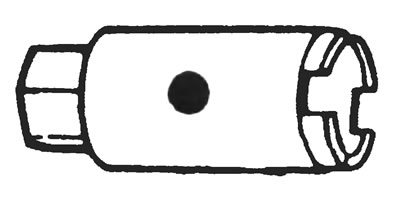
Figure 25.13. Ford special tool #13-011, which is recommended for use in place of a socket wrench when removing the sliding sleeve and lower pinion bearing caps.
15. Move the steering rack to the opposite side, remove the gear from the steering gear housing. When removing, pay attention to the orientation of the pinion shaft guide spline. If the gear itself or its bearings are damaged or heavily worn, the assembled gear should be replaced with a new one without disassembling it.
16. Remove the steering rack from the steering gear housing. Carefully remove the steering rack support bearing.
17. The steering gear bearings and seal can be knocked out of the steering gear housing using a suitable punch.
18. Clean, inspect and replace all components with new ones if necessary. Clean the sliding bushing cover and steering gear housing. Wash and sand the steering rack pipe hangers before assembly.
19. Insert the steering rack support sleeve into the steering gear housing, ensuring that the tabs are properly engaged.
20. Tap the pinion seal and rear main bearing into place until the bearing is flush with the seal flange (see Figure 25.20).
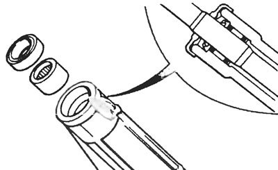
Figure 25.20. Install the pinion seal and rear main bearing so that the bearing is flush with the seal flange.
21. After lubricating the bearings, bushings and seals with the specified lubricant, insert the steering rack into the housing and position it so that all its teeth are visible.
22. Install the gear and bearing. While moving the steering rack inside the housing, engage the steering pinion so that when the steering rack is located strictly in the center of the housing, the guide spline of the pinion is positioned as noted during removal (see figure 25.22).
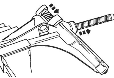
Figure 25.22. Installing gear and bearings.
23. After filling the steering gear housing with the specified grease, install the pinion bearing cover and tighten it to the specified torque. Tap the edges of the cover to the crankcase with a center punch or chisel to secure it.
24. Set the rack in the middle position by rotating it, from which, when rotating in any direction, the number of revolutions of the gear to the required stop is equal to half the number of revolutions of the gear required to move from stop to stop, and clean the threads of the housing and the rack stop from grease.
25. Install the stop with the spring into the crankcase, lubricate the stop threads with sealant and install the stop, tightening it to the tightening torque specified in the specification. Move the steering rack five times in each direction through its full working stroke to adjust it, then unscrew the cover by 30°.
26. Using a suitable torque wrench or preload gauge, check the pinion torque. Center the steering rack, turn the pinion one turn counterclockwise, then two turns clockwise, recording torque readings. Next, return the rack to the center position by turning the pinion one revolution counterclockwise. The torque at the center position of the rack must comply with the specification. If necessary, rotate the rack stop 50° in either direction (from the "minus 30°" position). When sliding the steering rack, you should not feel any wobble between the rear of the steering rack and the rack stop.
27. Secure the rack stop and gear stop in the housing using a chisel at three points around the perimeter.
28. Move the steering rack to the side to expose the teeth, then place the steering gear in a vice to clamp the steering rack teeth.
29. Screw the ball joints of the steering rods to the steering rack and tighten them. Press the edges of the coupling flanges into the steering rack groove to secure them. Using a pipe wrench to tighten the hinges, remove any burrs by filing them smooth with a file.
30. Install the rubber protective boots for the left gear, securing them with new clamps.
31. After filling the gear protective cap with the specified lubricant, slide it over the gear shaft onto the housing so that it contacts the upper edge of the seal.
Installation
32. Installation is carried out in the reverse order of removal, but before connecting the column universal joint, set the steering wheel and front wheels to the straight ahead position. On a new steering gear, to calculate the straight ahead position, divide by two the number of turns required to move the steering rack from one stop to the other. Use a new pressure plate bolt when installing the universal joint. Tighten nuts and bolts to specification and install new cotter pins (where provided). Finally, check and, if necessary, adjust the front wheel alignment as described in Section 36.