Contents: General information about ECU… ↳ Crankshaft position and speed sensor ↳ Coolant temperature sensor ↳ Air temperature sensor ↳ Accelerator pedal position sensor ↳ EGR vacuum regulator ↳ ECU (electronic control unit) ↳ Crankshaft position and speed sensor ↳ Coolant temperature sensor ↳ Air temperature sensor ↳ Accelerator pedal position sensor ↳ Manifold pressure sensor ↳ Vacuum regulator on the EGR valve ↳
General information about ECU (electronic control unit)
1. This device is the heart of the engine management system, controlling fuel injection and reducing toxicity (and recirculation) exhaust gases. The ECU receives signals from various sensors that monitor changes in engine operating conditions; inlet air and coolant temperatures, engine speed, accelerator pedal position, etc. These signals are used by the ECU to determine the fuel delivery mode.
2. The system is similar to the central nervous system in the human body - sensors (nerve endings) constantly signal to the ECU (brain), which processes the data and, if necessary, gives a command to change the operating parameters of the engine (body) via the actuators (muscles).
Crankshaft position and speed sensor
3. This is an inductive pulse generator attached to the cylinder block or crankcase that monitors the passage of the jumpers in the flywheel. Each time a jumper passes near the sensor, a signal is generated that is used by the ECU to determine the engine speed.
4. Opposite one of the holes there is no jumper, which allows the ECU to determine the position of the crankshaft (and, accordingly, the piston).
Coolant temperature sensor
5. This component is a negative temperature coefficient thermistor, that is, a semiconductor whose electrical resistance decreases with increasing temperature. In this way, the ECU receives an analog electrical signal, the value of which is proportional to the coolant temperature. This is used to refine the calculations made by the ECU when determining fuel consumption.
Air temperature sensor
6. This sensor is also a negative temperature coefficient thermistor (see previous paragraph) - sends a signal to the ECU corresponding to the temperature of the air entering the engine. This is also used to refine the calculations made by the ECU when determining fuel consumption.
Accelerator pedal position sensor
7. The presence of this sensor ensures electronic control of fuel supply. The accelerator cable is connected to the accelerator pedal position sensor, which converts the movement of the pedal into an electrical signal (on later models, the sensor is part of the ice mechanism). Processing this signal (and refining it using information received from other sensors), The ECU electronically controls the high-pressure fuel pump so that the amount of fuel injected is perfectly matched to the desired speed. Manifold pressure sensor.
8. This sensor measures the vacuum in the exhaust manifold and provides this information to the ECU to calculate the relationship between the accelerator pedal position and the amount of fuel injected.
EGR vacuum regulator
9. Before reaching the EGR valve, the vacuum from the exhaust manifold passes through a vacuum regulator mounted on the firewall of the engine compartment. The vacuum regulator changes the vacuum supplied to the EGR valve according to information received from the ECU.
Examination
10. The various components of the fuel system are so closely linked to the control system that fault diagnosis is almost impossible to achieve using traditional methods. While in traditional systems an experienced mechanic can quite accurately determine the cause of a malfunction and quickly fix it, in the case of an integrated engine management system this is hardly possible in most cases, since even a minor malfunction can have many symptoms
11. To ensure that the causes of faults can be quickly and accurately traced and corrected, the ECU is equipped with a built-in self-diagnostic program that detects faults in system components. In the event of a malfunction, the ECU not only recognizes the malfunction by storing the corresponding code in its memory, but also (in most cases) controls the system using the backup capabilities stored in its memory, which allows you to maintain control of the car and bring it to the garage for a detailed inspection.
12. All possible faults have a corresponding two- or three-digit code, which allows you to determine the location of the fault when connecting the system (via the built-in analyzer or self-test connectors) to special diagnostic equipment. Obviously, accurate interpretation of these fault codes requires specialized diagnostic test equipment and experience with it. Even if it is known that one of the sensors is faulty, a thorough check using special equipment is required. Therefore, in such cases, please contact your Ford dealer.
Removal and installation. General part
13. Before removing any components, disconnect the negative battery cable.
ECU (electronic control unit)
Caution: ECU is a very fragile device. Protect it from drops and impacts, exposure to extreme temperatures and moisture.
14. On pre-1995 models, turn the two retaining latches counterclockwise, lightly press the ECU cover forward and down, and remove the unit and cover (see Figure 27.14).
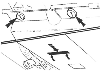
Figure 27.14. Location of retaining latches and sequence for removing the ECU cover.
15. Push the retaining clip inward to release it from the slot and pull the device upward.
16. Pull out the multi-pin plug clamp and disconnect the plug. Remove the ECU.
17. Installation is carried out in the reverse order of removal
18. On later models, unscrew the two locking nuts from the rubber boot of the multi-pin plug on the bulkhead, move the boot away, and disconnect the multi-pin plug
19. Using a screwdriver and a soft pad, carefully pry up the unit cover at the top of the passenger side dash.
20. Through the resulting opening, unscrew the bracket bolts and remove the ECU
21. Installation is carried out in the reverse order of removal.
Crankshaft position and speed sensor
22. The crankshaft position and speed sensor is located at the rear of the engine, slightly above the starter.
23. Disconnect the multi-pin plug, unscrew the fixing bolt and remove the sensor. Remove the gasket behind the sensor if one is installed.
24. Installation is carried out in the reverse order of removal. Make sure the gasket (where it is installed) placed behind the sensor
Coolant temperature sensor
25. Drain the cooling system (see Chapter 1).
26. Disconnect the electrical connector from the sensor located on the thermostat housing.
27. Unscrew the sensor and remove it.
28. Installation is carried out in the reverse order of removal. Apply a thin layer of sealant to the sensor threads before installation and fill the cooling system with fluid (see Chapter 1) upon completion
Air temperature sensor
29. To access the sensor, remove the air filter (see section 3) or air intake tube, if necessary.
30. Disconnect the multi-pin plug and then unscrew the sensor from the air filter housing.
31. Installation is carried out in the reverse order of removal.
Accelerator pedal position sensor
32. On pre-1995 models, remove the two retaining nuts and pull the accelerator pedal position sensor out of the engine compartment along with the support bracket (see figure 27 32).
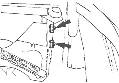
Figure 27.32. Unscrew the two fixing nuts (indicated by arrows) and remove the accelerator pedal position sensor retaining bracket together with the sensor.
33. Disconnect the accelerator cable from the sensor.
34. Disconnect the multi-pin plug, unscrew the two lock nuts and separate the sensor from the bracket.
35. Installation is carried out in the reverse order of removal
36. On the model since 1995, the sensor is built into the gas pedal and is removed together with it (see Section 14).
Manifold pressure sensor
37. The sensor is located on a bracket attached to the bulkhead at the rear of the engine compartment (see figure 27.37).
38. After unscrewing the bolts of the support bracket, lower it.
39. Disconnect the multi-pin plug and separate the vacuum hose from the sensor housing.
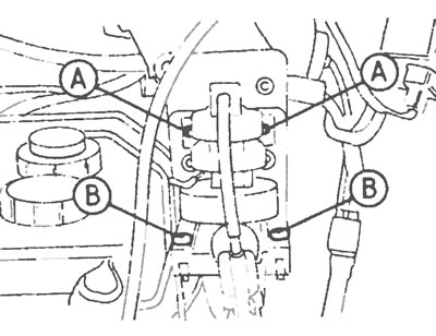
Figure 27.37. Manifold pressure sensor (B) and vacuum regulator (A) fixing bolts.
40. Unscrew the two fixing screws and separate the sensor from the bracket.
41. Installation is carried out in the reverse order of removal.
Vacuum regulator on the EGR valve
42. The vacuum regulator is mounted on the same bracket as the manifold pressure sensor (see figure 27.37). Removal and installation procedures are the same as for the manifold pressure sensor described in the previous subsection.
The original article is available on the website: FordBook