Contents: Crankcase ventilation system ↳ Exhaust emission control system ↳ Exhaust gas recirculation system ↳ EGR valve - non-turbocharged engines ↳ EGR valve - turbocharged engines ↳ Intercooling - Turbocharged Engines… ↳
Crankcase ventilation system
Examination
1. If you think the system is faulty, first make sure that there is no deposit on the hoses. If the vehicle has high mileage, especially if it has been used regularly for short trips, a gelatinous deposit may form on the internal crankcase ventilation hoses or on the oil filler cap. If excessive deposits are present, the appropriate hose or cap must be removed or cleaned.
2. Periodically inspect the system hoses for security or damage and replace them with new ones as necessary. Please note that leaking or dirty hoses can cause various types of engine problems (erratic engine speed at idle, stalling, etc.), the causes of which are usually difficult to trace.
Replacement of parts
3. The sequence for replacing the hoses and the oil filler cap is self-evident.
Exhaust emission control system
Examination
4. The system can only be tested with an appropriate gas analyzer.
Replacement of parts
5. The catalytic converter is installed between the exhaust manifold and the muffler downpipe.
6. Removal and installation of the neutralizer as part of the exhaust system is described in section 23.
Exhaust gas recirculation system
Examination
7. The system must be checked and adjusted by a Ford dealer.
Replacement of parts
EGR valve - non-turbocharged engines
8. Loosen the two Torx bolts or clamping ring to separate the EGR system connection hose from the EGR valve and exhaust manifold and remove the metal gasket. Where necessary, unscrew the bolt of the support bracket of the hose or pipe connecting the EGR system (see Figure 25.8, a-c).
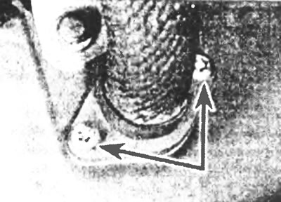
Figure 25.8a. Separate the EGR hose from the exhaust manifold by loosening the two Torx bolts (indicated by arrows).
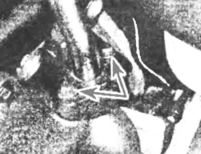
Figure 25.8b. Connecting the EGR pipe to the exhaust manifold on the latest models...
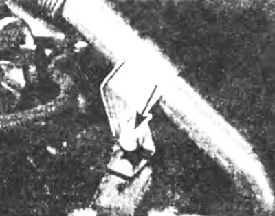
Figure 25.8c....and the location of the pipe fixing bracket bolt (indicated by the arrow).
9. Loosen the hose clamp and separate the air supply hose from the throttle body (see Figure 25.9).
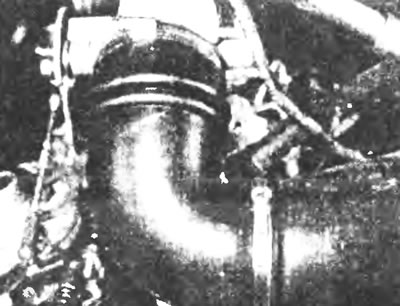
Figure 25.9. Loosen the hose clamp and separate the air supply hose from the throttle body.
10. Disconnect the throttle control lever from the throttle control mechanism.
11. On engines with a one-piece intake manifold, disconnect the EGR valve vacuum hose, unscrew the two bolts and separate the throttle body (together with the valve) from the intake manifold (see Figure 25.11). Remove the four Torx bolts and separate the EGR valve and connecting hose from the throttle body.
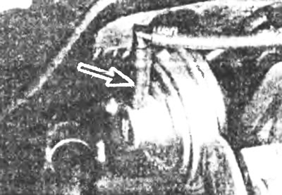
Figure 25.11. Disconnect the EGR valve vacuum hose.
12. On engines with a two-piece split intake manifold, remove the bolt securing the manifold to the support bracket. Unscrew the nuts and bolts and separate the upper part of the manifold from the lower part. Remove the gasket between the two halves. Disconnect the EGR valve vacuum hose, then remove the four Torx bolts, separate the EGR valve and connection hose from the throttle body.
13. Installation is carried out in the reverse order of removal. Use new gaskets at the manifold and EGR valve joints and tighten all nuts and bolts to specification.
EGR valve - turbocharged engines
14. Loosen the hose clamps and disconnect the air supply pipe at the hose connection on the intake manifold.
15. Unscrew the bolts, separate the air intake pipe connection on the turbocharger side and remove the gasket. Separate the pipe from the support bracket and remove it. Cover the turbo inlet using a suitable cap or rag.
16. Disconnect the EGR valve plug and vacuum hose.
17. Remove the two Torx bolts and throttle body together with the EGR valve, remove the two remaining Torx bolts and separate the valve from the housing.
18. Installation is in order. reverse removal. Use new gaskets and tighten all nuts and bolts to specification.
Intercooling - Turbocharged Engines (since 1995)
19. Disconnect the negative battery cable.
20. Contact Chapter 1, drain the liquid from the cooling system.
21. Unscrew the two bolts, disconnect the EGR system connecting pipe from the exhaust manifold and remove the metal gasket.
22. Loosen the clamp bolt and remove the clamp securing the other end of the EGR system connecting pipe to the intercooler radiator. Remove the pipe.
23. Disconnect the plug and vacuum hose of the EGR valve.
24. Unscrew the two Torx bolts, remove the EGR valve and take out the metal gasket.
25. Loosen the clamps and disconnect the coolant hoses from the radiator (see figure 25.25).
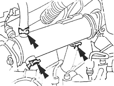
Figure 25.25. Disconnect the clamps (indicated by arrows) and coolant hoses from the intermediate cooling radiator.
26. Unscrew the bracket and flange fixing bolts and remove the radiator.
27. Installation is carried out in the reverse order of removal, use new gaskets if necessary.