Contents: Removal ↳ Installation ↳
Removal
1. Remove the front wheel hub as described in Section 12.
2. After unscrewing the nuts, remove the bolts securing the lower steering arm to the steering knuckle and remove the arm (see Figure 14.2).
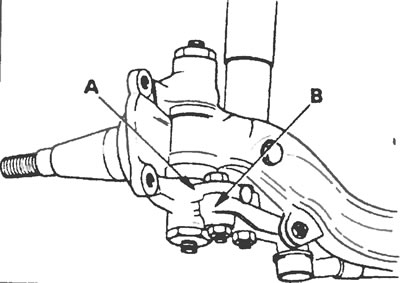
Figure 14.2. Bolts fastening the steering knuckle (A) and the lower steering arm (B) together.
3. Remove the union nuts with plugs from the kingpin grease fittings from the steering knuckle (see Figure 14.3).
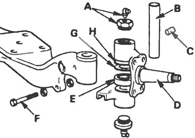
Figure 14.3. Detailed view of the steering knuckle: A - Grease nipple and nut, B - Kingpin, C - Locking pin, D - Steering knuckle, E - Lower bearing, F - Wheel stop bolt, G - Gasket, H - Seal
4. Remove the retaining pin that passes through the front axle beam and remove the kingpin. Sometimes it may be necessary to use a press or punch to remove the cotter pin, which in turn may require removing the front axle beam.
5. Remove the steering knuckle and gasket.
6. If the steering knuckle is to be repaired, remove the upper cylinder seal and the lower steering knuckle bearing.
7. Remove the steering knuckle on the other side in the same way, but store the right and left knuckle components separately.
8. Remove the front wheel steering limiter bolts only as a last resort, as they require adjustment with special tools during installation and must be reinstalled by a Ford dealer.
9. Thoroughly clean the contact surfaces of the steering knuckle and front axle beam with paraffin and wipe with a smooth cloth. Inspect them for deformation or damage. If you have any doubts about their condition, contact your Ford dealer for inspection and replacement of worn components.
10. If the kingpin is to be replaced with a new one, the kingpin pivot bolt bushings should also be replaced with new ones. Since the procedure for removing and installing bushings requires the use of specialized equipment, it is best to entrust their replacement to a local Ford dealer.
Installation
11. With all new bushings, lower bearing and upper cylinder seal in place, position the steering knuckle against the front axle beam. Select a new shim of the required thickness and insert it between the top surface of the beam eye and the upper cylinder of the steering knuckle (see Figure 14.11). Measure the required shim thickness using a feeler gauge and select a shim that will provide the specified runout between the steering knuckle and the front axle beam.
12. After lubricating the kingpin with grease, insert it from above into the steering knuckle and beam and push it down just enough to insert the gasket. Insert the shim, then push the kingpin back up, lining up the notch in the kingpin with the cotter pin hole in the beam.
13. Insert the new cotter pin flush with the beam.
14. Install the upper and lower union nuts with grease plugs. Lubricate the kingpin on both sides and check its operation. If it is difficult to turn, you may need to install a thinner shim. If the rotation seems too easy, install a thicker gasket. Recheck the runout between the steering knuckle and the front axle beam.
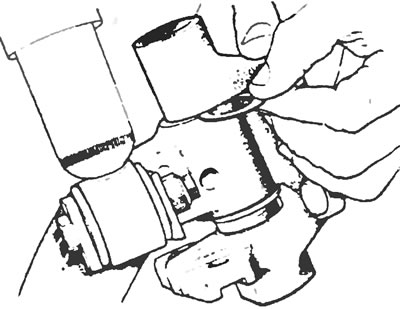
Figure 14.11. Insert a new gasket of the required thickness between the top surface of the beam eye and the upper cylinder of the steering knuckle.
15. Install the lower steering arm onto the steering knuckle and tighten the retaining nuts to specification.
16. Having installed the front wheel hub (see Section 12), check and adjust the axial runout.