Contents: Removal ↳ Installation ↳
Removal
1. The front axle beam can be removed either fully assembled or partially disassembled; if the kingpins are jammed, it is preferable to remove them together with the beam, then separating them with a hydraulic press.
2. With the parking brake applied, loosen the wheel nuts on the front wheels (remember that the nuts on the left side have left-hand threads - they should be unscrewed clockwise). Jack up the front of the car and secure it to the supports installed on the sides of the chassis. Support the front axle beam with a jack and supports.
3. Unscrew the wheel nuts and remove the front wheels.
4. After unscrewing the nuts and removing the mounting bolts, disconnect the front shock absorbers from the beam (see Figure 15.4).
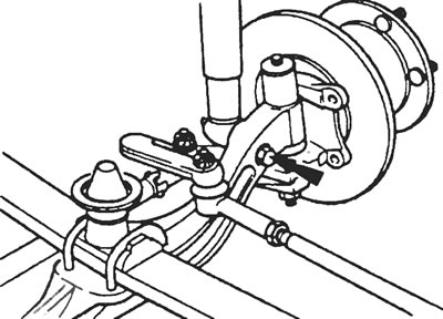
Figure 15.4. Bolt securing the shock absorber to the steering knuckle.
5. After removing the cotter pin, unscrew the castle nut securing the longitudinal steering rod to the steering knuckle arm. Release the tie rod using a suitable ball joint puller.
6. After unscrewing the fixing bolts, remove the brake calipers together with the brake pads from the steering knuckles. The hydraulic hoses do not need to be disconnected from the calipers, but each caliper must be suspended or supported so that the hoses do not stretch or kink.
7. If an anti-roll bar is installed, unscrew the lock nuts of the bolts and remove the stabilizer U-bolts with the cushions (see Figure 15.7).
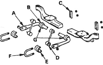
Figure 15.7. Anti-roll bar and its fasteners: A - Anti-roll bar, B - Bar pad, C - Anti-roll plate, D - Post, E - Rubber pad, F - Step ladder, G - Inner edges between which the distance must be measured.
8. Unscrew the fixing nuts and remove the U-bolts connecting the spring (and also a travel limit buffer) with front axle beam. Make sure the beam is securely supported on both sides before detaching the ladders (see Figure 15.8).
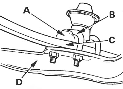
Figure 15.8. Fastening the front spring to the front axle beam: A - Overlay, B - Spring U-bolt, C - Front spring, D - Front axle beam
9. With the help of an assistant, lower the beam and remove it from the front of the vehicle.
10. If required, the front axle can be disassembled further as described in the relevant sections of this Chapter.
11. If there is a suspicion that the front axle is deformed, it must be inspected in a suitably equipped garage and, if necessary, repaired.
Installation
12. Installation is carried out in the reverse order of removal, but the following additional points should be noted:
- a) When installing the front axle beam in its original position, the spring mounting pin must align with the hole in the beam (see Figure 15.12), then insert the U-bolts and tighten the nuts to the specified tightening torque (the nuts should be tightened in three stages as indicated in specifications at the beginning of this Chapter).
- b) Make sure that the shock absorber retaining bolts are installed with their heads facing the front of the vehicle;
- c) If there is an anti-roll bar, make sure that the rubber pads of the anti-roll bar are located at an equal distance from its curved edges, and that the distance between the inner edges of the inserts is 620 mm;
- d) Tighten all fasteners to the specified torque values and, where a cotter pin is used, turn a little further to the nearest position that will allow the cotter pin to be inserted. Always use new cotter pins when securing parts.
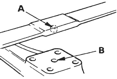
Figure 15.12. When installing the front axle beam in its original position, the spring mounting pin (A) must align with the hole in the beam (B) of the bridge.
[The original can be found on this resource: FordBook.ru]