Contents: Removal ↳ Installation ↳
Removal
1. Apply the parking brake, loosen the corresponding wheel nuts, then jack up the front of the vehicle and support it on stands.
2. Unscrew the nuts and remove the wheel on the side you are interested in.
3. Unscrew the bolt and separate the bracket holding the front brake hose from the shock absorber.
4. Place a jack or support under the lower control arm (the contact area must be dry). Make sure the jack or support is positioned so that the three retaining nuts are accessible (or bolt heads) ball joint on the back of the lower suspension arm.
5. Unscrew the four bolts and separate the shock absorber from the steering knuckle. Support the steering knuckle assembly to prevent deformation of the lower control arm ball joint.
6. Remove the cotter pin (if there is one) and unscrew the nut securing the ball joint of the lower arm to the steering knuckle (see Figure 9.6.). If the ball pin turns, push the steering knuckle down hard. This will grip the ball joint cone, preventing it from turning. On later models, insert a 9mm socket wrench into the top of the ball stud to hold the stud in place while you remove the nut.
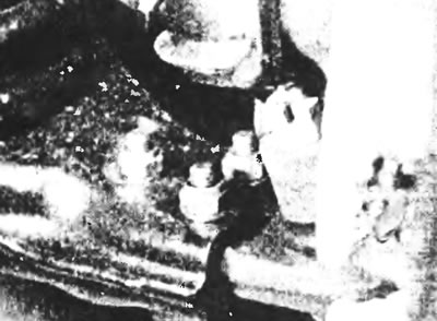
Figure 9.6. Nuts securing the ball joint to the lower suspension arm and to the steering knuckle.
7. After removing the nut, release the ball joint cone using a suitable ball joint puller or a two-pronged puller, being careful not to damage the protective boot. Move the steering knuckle up, removing it from the ball joint pin.
8. Remove the three retaining nuts, bolts and separate the ball joint bearing (assembly) from the lower control arm.
Installation
9. Insert the ball joint bearing into the recess in the control arm, being careful not to damage the protective boot. Please note that if you accidentally insert the bearing too far, the cover can easily be damaged.
10. Insert the three ball joint retaining bolts, screw on the nuts and tighten them to the specified torque.
11. If the ball joint is secured to the steering knuckle with a castle nut and cotter pin, to facilitate installation of a new cotter pin, rotate the ball joint rod so that the hole for the cotter pin forms an angle of 90° with the steering knuckle journal.
12. After ensuring that the mating surfaces are clean, place the steering knuckle onto the ball joint pin.
13. Install the retaining nut and tighten it to the specified torque, holding the ball stud from rotating as described above.
14. If a castle-type lock nut is used, secure the nut with a new cotter pin. If necessary, tighten the nut a little more to align the grooves in the nut with the cotter pin hole in the ball stud.
15. With the shock absorber positioned against the steering knuckle, insert the four bolts and tighten them to the specified torque. Remove the jack or support from under the lower control arm.
16. Connect the brake line to the bracket on the shock absorber.
17. Once completed, install the wheel and lower the vehicle to the ground.
18. Tighten the wheel nuts to the specified torque.
(For more information, please visit the website: fordbook.ru)