Remember: if the bushings of both the right and left brackets require replacement, the brackets must be removed and installed alternately. If at any point both brackets are removed, the suspension geometry will be compromised and will require inspection (and possibly regulation), which must be produced by a Ford dealer.
1. With the parking brake applied, jack up the front of the vehicle and support it on jack stands.
2. Disconnect the anti-roll bar, if equipped, from the suspension arm (see Section 10).
3. Unscrew the nuts and washers securing the brackets to the chassis (see Figure 8.3). Place a jack under the bracket, jack it up enough to support its weight, and remove the bolt. Then lower and remove the jack.

Figure 8.3. Detailed view of the lower suspension arm mount to the front bracket: A - Bolt securing front bracket to chassis, B - Front bracket, C - Crossmember, D - Pin, E - Bolt securing front bracket to crossmember, F - Torx mounting bolts, G - Bolt securing lower control arm to front bracket, H - Lower (transverse) suspension arm, I - Front bracket bushing, J - Belleville washer, K - Nut, L - Cotter pin.
4. Remove the cotter pin and unscrew the nut connecting the lower arm and the front bracket. Remove the washer and bolt.
5. Remove the two Torx bolts that secure the suspension bracket to the crossmember and remove the front suspension retaining bolt. Now you can separate the front bracket from the cross member (removing from the pins) and remove.
6. To remove the bushing from the front bracket, lightly clamp the front bracket in a vice with rubber pads so that the bushing is on top, then press the bushing out with a puller (see Figure 8.6). You can also press out the bushing using a piece of metal pipe of a suitable diameter and a long bolt with a nut and washers.
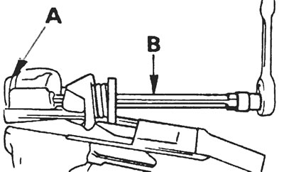
Figure 8.6. Removing the lower control arm bracket bushing using a two-legged puller.
7. Before inserting the new bushing, thoroughly clean the bushing eyes. After lubricating the eye and bushing with engine oil, press the bushing into the installation position with a vice, using a piece of pipe as a spacer (see Figure 8.7). Once the bushing is installed, make sure that its edge tabs protrude from both sides of the front bracket.
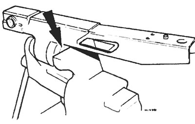
Figure 8.7. Pressing in a new bushing (shown by the arrow) into the eye of the lower suspension arm.
8. Install the front bracket to the chassis and connect the remaining parts in the reverse order of removal, paying attention to the following additional points:
- a) Make sure the bracket is fully seated on its pins before tightening the retaining nuts and bolts;
- b) The suspension arm pivot bolt washer must be installed with the convex side facing the suspension bushing. Do not tighten the locking nut completely (up to the tightening force specified in the specification), until the car stands freely on all wheels. After this, a new cotter pin can be inserted to secure the nut in place;
- d) Insert the bolts securing the crossmember to the chassis and the two Torx bolts and tighten them by hand. Then (jack up the front bracket to align the bolt holes) insert the bolts securing the front bracket to the chassis and tighten them to specification. Remove the jack and only then tighten the bolts securing the cross member to the chassis to the tightening torque specified in the specification;
- d) Turning to Section 10, connect the anti-roll bar (if it was originally installed).
[The original source of the publication is on the website: FordBook]