Contents: Throttle body ↳ Endura-E Engines ↳ RTE engines ↳ Zetec and Zetec-E engines ↳ Fuel line and fuel injectors ↳ Fuel pressure regulator ↳ Idle speed control valve ↳ Air flow sensor ↳ ECU Block ↳ Camshaft Position Sensor ↳ Incoming air temperature sensor ↳ Throttle Position Sensor ↳ Vehicle speed sensor ↳ Power Steering Pressure Sensor ↳ Oxygen sensor ↳
Throttle body
Relieve the pressure in the fuel system and equalize the pressure in the tank with atmospheric pressure by removing the fuel filler cap.
Remove the negative terminal from the battery.
Endura-E Engines
Remove the engine air supply components. Disconnect the accelerator cable from the throttle.
Disconnect the throttle position sensor electrical connector.
Label and disconnect the vacuum hoses from the throttle body.
Unscrew the throttle body mounting screws, remove it and the gasket from the intake manifold.
Installation is performed in the reverse order of removal. Before installing the gasket, clean the mating surfaces of the throttle and intake manifold.
RTE engines
Remove the engine air supply system components. Disconnect the accelerator cable from the throttle.
Unscrew the bolts and remove the accelerator cable housing suspension bracket in the throttle body.
Disconnect the vacuum hoses from the intake manifold and fuel pressure regulator.
Remove the connectors from the idle speed control valve, temperature sensor and harnesses.
Disconnect the fuel return hose from the pressure regulator.
Unscrew the throttle body mounting bolts and remove it together with the gasket.
Installation is performed in the reverse order of removal. Before installation, clean the mating surfaces of the throttle body and intake manifold. Install a new gasket.
Zetec and Zetec-E engines
Remove the engine air supply system components. Disconnect the accelerator cable from the throttle.
Disconnect the electrical connector from the throttle position sensor.
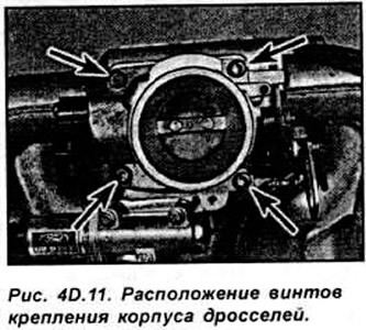
Unscrew the throttle body mounting screws, remove it and the gasket (see Fig. 4D.11).
Installation is performed in the reverse order of removal. Before installation, clean the mating surfaces of the throttle body and intake manifold.
Fuel line and fuel injectors
The sequence of operations related to Zetec and Zetec-E engines is given.
Relieve the pressure in the fuel system and equalize the pressure in the tank with atmospheric pressure by removing the fuel filler cap. Remove the negative terminal from the battery.
Remove the engine air supply system components. Disconnect the accelerator cable from the throttle.
Disconnect the throttle position sensor electrical connector.
Unscrew the throttle body mounting screws and remove it along with the gasket from the intake manifold.
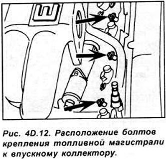
Remove the crankcase ventilation hose from the cylinder head cover and the vacuum hose of the pressure regulator from the exhaust manifold. Loosen the wiring harness fastening clips, disconnect the 4 connectors from the fuel injectors and the connector of the intake air temperature sensor. Disconnect the supply and return fuel pipes. Unscrew the 3 fuel line fastening bolts, remove it from the intake manifold using a lever (see Fig. 4D.12).
Secure the fuel line in a vice with soft jaws, unscrew the 2 bolts securing each fuel injector and remove them.
When replacing fuel injectors, be sure to replace the O-rings. Installation is performed in the reverse order of removal.
- lubricate the O-rings with engine oil before installation;
- install the fuel injectors into the recess in the fuel line, aligning the protrusion on the fuel injector head with the groove in the fuel line. Tighten the injector mounting bolts to the specified torque;
- install new o-rings onto the fuel injector nose and take care to ensure the o-ring does not move when installing the fuel line;
- check that the hoses and electrical connectors are connected correctly;
- adjust the accelerator cable;
- finally, turn on the ignition about 5 times so that the fuel pump creates pressure in the fuel system. Check the tightness of the fuel system.
Fuel pressure regulator
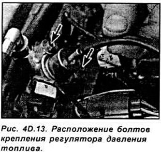
Relieve the pressure in the fuel system and equalize it with atmospheric pressure in the tank by removing the fuel filler cap. Remove the negative terminal from the battery. Disconnect the vacuum hose from the regulator.
Unscrew the 2 regulator mounting bolts and remove it (see Fig. 4D.13).
Installation is carried out in the reverse order of removal:
- before installing the regulator in place, replace the O-ring and lubricate it with engine oil;
- carefully install the regulator into the fuel line and secure with bolts;
- turn on the ignition about 5 times so that the fuel pump creates pressure in the fuel system. Check the fuel system for leaks;
Idle speed control valve
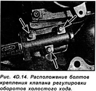
Remove the negative terminal from the battery. Disconnect the electrical connector from the valve.
Unscrew 3 bolts and remove the valve from the intake manifold (see Fig. 4D.14).
Installation is carried out in the reverse order of removal.
- clean the mating surfaces and install a new gasket;
- start the engine and warm it up to operating temperature. Check the idle speed and stability, then turn on all electrical consumers and check that the idle speed does not change.
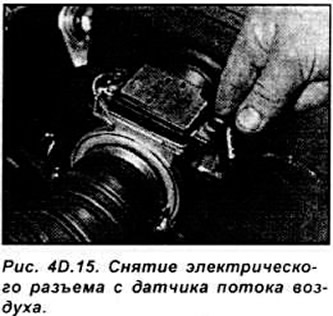
Air flow sensor
Disconnect the bracket and remove the electrical connector from the sensor (see Fig. 4D.15).
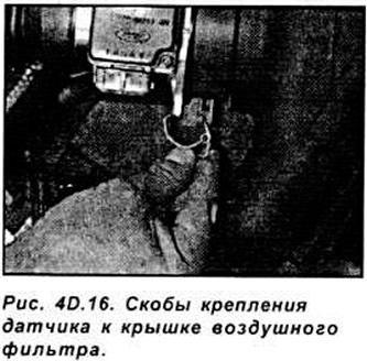
Release the 2 clips and separate the sensor from the air filter cover (see Fig. 4D.16).
Loosen the clamp and disconnect the sensor from the air supply hose. Remove the sensor.
Installation is carried out in the reverse order of removal.
ECU Block
Working inside the vehicle, remove the trim from the front lower portion on the passenger side to access the ECU.
Release the ECU unit from the holder. Unscrew the mounting screws and remove the electrical connector.
Installation is carried out in the reverse order of removal.
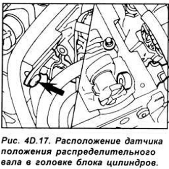
Camshaft Position Sensor
Release the fuel supply and return hoses from the mounting brackets. Release the electrical wires from the mounting bracket and remove the connector from the camshaft position sensor. Unscrew the mounting screw and remove the sensor from the cylinder head (see Fig. 4D.17).
Installation is carried out in the reverse order of removal.
- before installing the sensor, lubricate the O-ring with engine oil;
- install the sensor into the cylinder head and wipe off any remaining grease;
- tighten the sensor mounting screw to the required torque.
Incoming air temperature sensor
The sensor is located in the air cleaner housing on Endura-E engines, in the intake manifold on RTE and Zetec engines, and in the engine air supply hose on Zetec-E engines.
Remove the air filter housing or the engine air intake duct system. Disconnect the electrical connector from the sensor, unscrew it and remove it together with the seal.
Installation is carried out in the reverse order of removal.
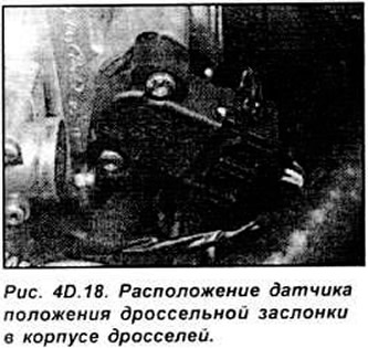
Throttle Position Sensor
Remove the air cleaner housing or the engine air intake duct system. Remove the electrical connector from the sensor, unscrew the mounting screws and remove the sensor from the throttle body. Do not rotate the central part of the sensor in the removed position, as it is very easy to damage (see Fig. 4D.18).
Installation is performed in the reverse order of removal. In this case, precisely align the cut on the throttle valve axis with the protrusion on the sensor. Tighten the sensor mounting screws evenly.
Vehicle speed sensor
The speed sensor is installed on the speedometer drive shaft and is removed together with the drive gear.
Power Steering Pressure Sensor
Remove the electrical connector from the sensor Unscrew it. Place a clean rag under the sensor to catch any leaking fluid. Check the condition of the sensor sealing ring and replace it if necessary.
Installation is performed in the reverse order of removal. If necessary, bring the fluid level up to the norm.
Oxygen sensor
Remove the electrical connector from the sensor wire.
Raise the front of the vehicle and secure it on stands. Unscrew the sensor from the exhaust pipe and remove it from underneath the vehicle (see Fig. 40.19).
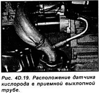
Installation is performed in the reverse order of removal. Lubricate the threaded part of the sensor with a non-stick compound.