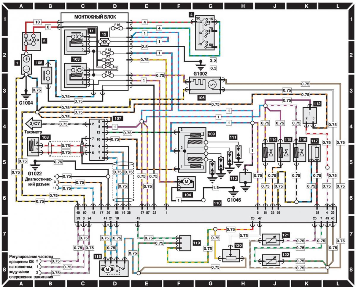
CFI Engine Management System (1996 and later models)
Open large image in new tab »
- 1 – battery;
- 4 – ignition switch;
- 5 – additional mounting block;
- 11 – relay;
- 12 – diode;
- 103 – Fuel pump relay;
- 104 – fuel pump;
- 105 – switch;
- 106 – oxygen sensor;
- 107 – DIS ignition control unit;
- 108 – crankshaft angle sensor;
- 109 – ignition coil;
- 110 – Fuel injection ECU;
- 111 – spark plugs;
- 112 – vehicle speed sensor;
- 113 – capacitor;
- 114 – electromagnetic valve of the idle speed system;
- 15 – purge valve of the adsorber;
- 116 – fuel injector;
- 117 – Fuel injector resistor;
- 118 – Throttle control motor;
- 119 – MAP sensor;
- 120 – throttle position sensor;
- 121 – intake manifold air temperature sensor;
- 122 – Coolant temperature sensor
General description and symbols on electrical diagrams are located here →
The original source of the publication is on the website fordbook