Contents: Bosch generators K1-55A and K1-70A ↳ Generator Bosch NC 14V 60-90A ↳ Generator Magneti-Marelli ↳ Mitsubishi Generator ↳
Remove the negative terminal from the battery. Remove the alternator from the engine.

Bosch generators K1-55A and K1-70A
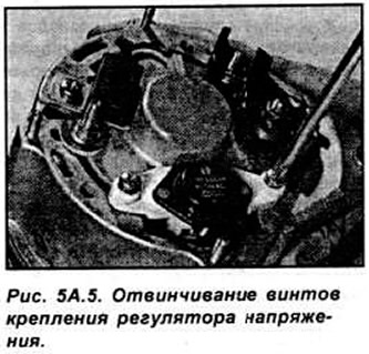
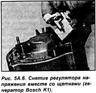
Unscrew 2 screws and remove the regulator with brushes from the rear of the generator (see Fig. 5A.5, 5A.6).
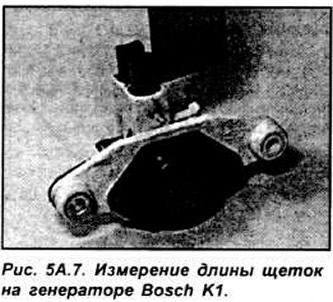
Check the length of the brushes. If it is shorter or close to the minimum, replace them by unsoldering the electrical connectors. Remove the brushes and springs. Clean the generator contact rings with a cloth dampened with solvent, check for wear and damage.
Installation is carried out in the reverse order of removal.
Generator Bosch NC 14V 60-90A
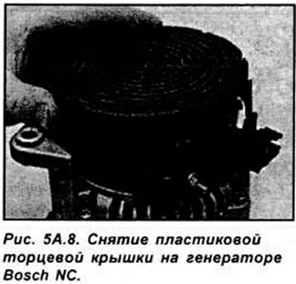
Unscrew 3 screws and remove the plastic end cover (see Fig. 5A.8).
Unscrew the 2 screws securing the voltage regulator with brushes.
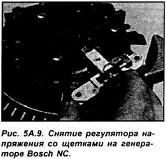
Remove the voltage regulator with brushes from the socket in the generator (see Fig. 5A.9).
Measure the length of the brushes. Check that each brush moves smoothly and without sticking in the socket.
Check that the alternator contact rings are clean. Wipe them with a cloth soaked in solvent and check for wear.
Installation is carried out in the reverse order of removal.
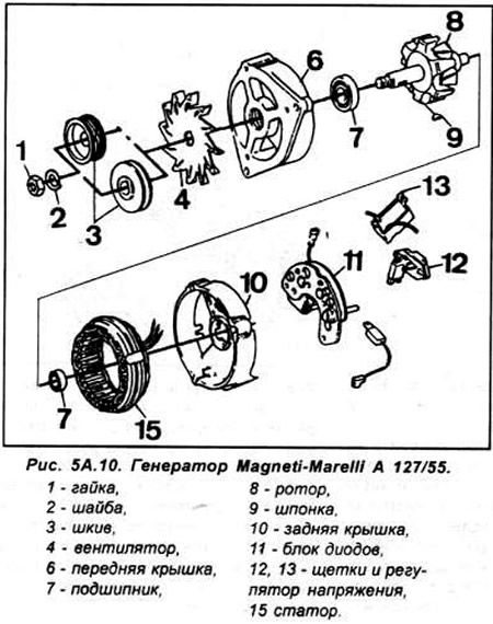
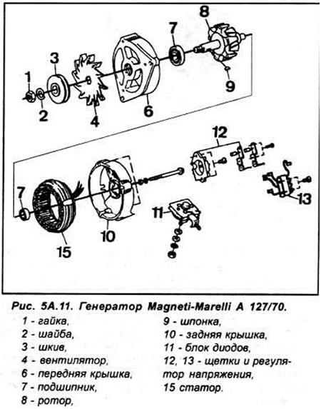
Generator Magneti-Marelli
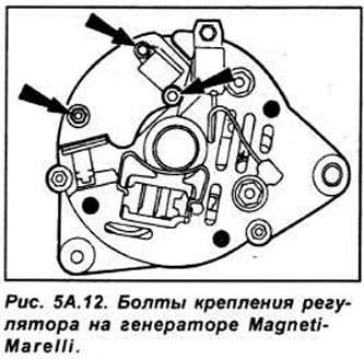
Unscrew the 3 screws securing the regulator with brushes from the rear of the generator and partially remove the regulator. Disconnect the connector and remove the regulator from the generator (see Fig. 5A.12).
Measure the length of the brushes. If the brushes are worn out, it is necessary to replace the entire voltage regulator with brushes, since the brushes are not supplied separately.
Clean the generator contact rings with a cloth dampened with solvent, then inspect the rings for wear and damage.
Installation is carried out in the reverse order of removal.
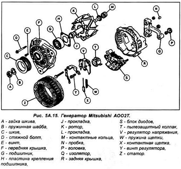
Mitsubishi Generator
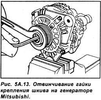
Secure the pulley and, using an 8 mm wrench, unscrew the pulley mounting nut (see Fig. 5A.13).
Remove the pulley, fan, gasket and clean the front cover of the generator.
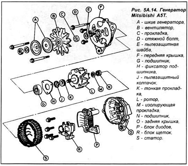
Mark the position of the stator front cover and the generator rear cover for proper reassembly. Loosen the tie bolts and remove the front cover from the rotor shaft.
Remove the rotor from the back cover and stator. If the stator cannot be removed, heat the back cover with a 200W soldering iron for 3-4 minutes.
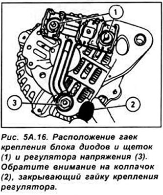
Unscrew the bolt securing the diode and brush assembly from the rear cover of the generator (see Fig. 5A.16).
Unsolder the stator and brushes from the diode assembly using a low temperature soldering iron.
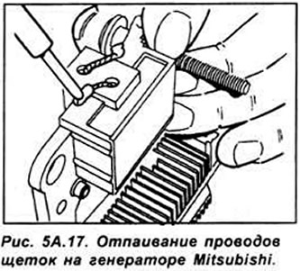
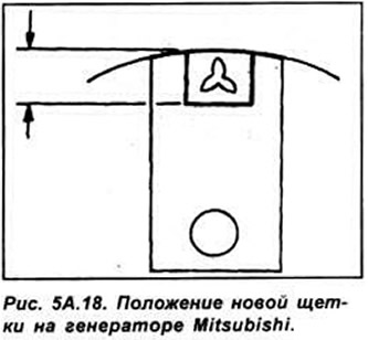
If the brushes are worn out, replace them. Unsolder the wires from the brushes at the designated points, then solder the new brush so that the soldering point does not extend beyond 2-3 mm from the end of the holder (see Fig. 5A.17, 5A.18).
Clean the generator contact rings with a cloth soaked in solvent. Check them for wear and damage.
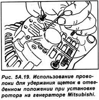
Installation is performed in the reverse order of removal. When installing the generator rotor, pull the generator brushes from the operating position through the opening in the rear cover (see Fig. 5A.19). After installing the rotor, release the brushes.
For more information, please visit the website: www.fordbook.ru