General information
The cooling system is a sealed type and includes a front-mounted radiator with horizontal tubes, a belt-driven water pump, a temperature-sensitive thermoviscous fan, a Wax-type thermostat, and an expansion tank (see figure 1.1).
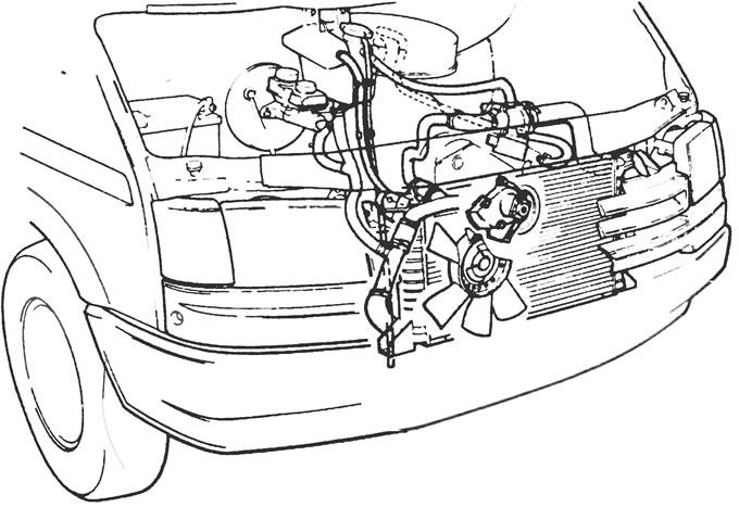
Figure 1.1. General arrangement of cooling system elements.
The radiator core has an aluminum construction, and the expansion tanks are plastic.
The thermostat is located in the housing on the front side of the cylinder head and is designed to ensure rapid engine warm-up by restricting the flow of coolant to the radiator when the engine is cold, and also to help regulate the engine's normal operating temperature.
The expansion tank has a pressure regulating cap that increases the pressure in the cooling system as the temperature rises, thus raising the boiling point of the coolant. It also performs a degassing function. Any air bubbles that accumulate in the coolant, particularly in the thermostat housing and radiator, are returned to the reservoir and released into the air, thus maintaining the effectiveness of the coolant.
The system functions as follows. Cold water at the base of the radiator passes through the bottom pipe to the water pump, where the pump impeller forces it through passages that surround the cylinder head and block. After cooling the cylinder liners, combustion chambers, and valve seats, the water reaches the back of the thermostat, which is initially closed. While the thermostat is closed, water returns through the radiator, cylinder head and block to the water pump. When the coolant reaches a certain temperature, the thermostat opens and it flows through the top hose to the top of the radiator. As the water passes through the radiator, it is cooled by the air flow generated by the vehicle's forward movement and amplified by the fan.
The water that reaches the base of the radiator is now cooled and the cycle repeats.
The fan is controlled by the air temperature behind the radiator. When the air temperature reaches a predetermined level, the bimetallic coil begins to open the valve and silicone fluid is supplied to the blades. Half of the blades are driven directly by the drive belt of the water pump and generator, and half are connected to the fan blades. The blades are designed in such a way that the engine torque is transmitted to the fan blades depending on the viscosity of the liquid, which in turn depends on the temperature and the engine speed. The fan is thus used only when required and, compared to direct drive fans, significantly reduces fuel consumption, drive belt wear and fan noise (see Figure 1.6).
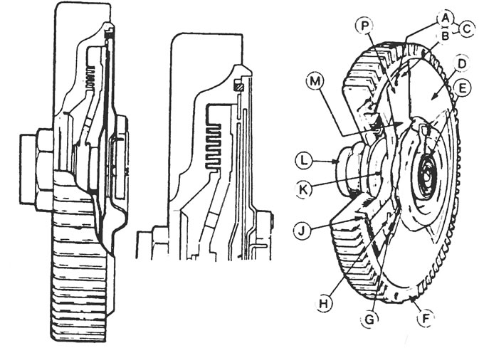
1.6. Fan with drive clutch assembly. Left - resting position: In the center - working condition, A - Drain hole, B - Drain, C - Plunger pump, D - Front casing, E - Bimetallic spring, F - Clutch housing, G - Check valve, H - Inlet hole, H - Seal, K - Rotor, L - Drive shaft, M - Liquid reservoir, P - Pump plate.
The heating and ventilation systems work in conjunction with the cooling system; the coolant passes through the radiator, transfers heat to the heating system and returns back to the engine cooling circuit. An electric fan, also located in the heater, supplies hot or cool air to the passenger compartment and to the windshield defroster vents as required.
Precautionary measures
Warning: Do not attempt to remove the coolant expansion tank filler cap, or any other part of the cooling system, if it or the engine is hot, as there is a very high risk of scalding. If it is necessary to remove the expansion tank cap before the engine and radiator have completely cooled down (although this is not recommended), the pressure in the system must be released. Cover the cap with a thick layer of cloth, avoiding scalding, and slowly unscrew the filler cap until the hissing sound stops. When the hissing stops, indicating that the pressure has been released, slowly unscrew the filler cap further and remove it, waiting for the hissing to stop, if it appears again.
Warning: Please refer to Section 12 and read the precautions given there if your vehicle is equipped with air conditioning.
(The original version can be found on the website: «www.FordBook.ru»)