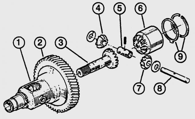
Fig. 12.11. Main gear and differential box: 1 – differential box; 2 – driven gear of the main transmission; 3 – output shaft and axle gear; 4, 7 – satellites; 5 – satellite finger; 6 – axle gear; 8 – satellite axis; 9 – intermediate and retaining rings
The main gear is designed to convert the rotation frequency of the secondary shaft into the corresponding frequency of the wheel drive shafts and, due to the differential, provides different rotation frequencies of the inner and outer drive wheels when driving in a turn (Fig. 12.11). The main gear pinion is connected with bolts to the differential box. The drive shafts form a connection with a force closure between the main gear and the wheel hub.
Main gear and wheel drive shafts
Main gear.
It is placed together with the differential and the manual gearbox or automatic gearbox STX in a common housing. Four bevel gears are in constant engagement in the differential box, two of which are connected to the drive shafts.
Move straight ahead.
The front wheels rotate synchronously with the main transmission. The differential rotates at the same frequency, the bevel gears are at relative rest.
Movement in a turn.
The wheel on the outside of the turn has a greater distance to travel than the wheel on the inside of the turn (rotational speed difference). If this difference is not compensated, the car will oversteer and the spinning inside front wheel will not fit into the turn.
Differential -
serves to distribute torque between the wheels and allows the drive shafts of the wheels to rotate at different angular velocities. The axle gears and satellites in the differential box provide the required compensation for the different angular velocities of the drive wheels. The rotation frequency of the axle gear connected by the drive shaft to the wheel on the outer radius of the turn is slightly higher than the rotation frequency of the differential box, as a result of which the satellites begin to rotate, which in turn reduce the rotation frequency of the axle gear connected to the wheel moving along the inner radius. The difference in angular velocities of the axle gears compensates for the difference in the path between both front wheels.
Transferring torque to the wheels (from the differential).
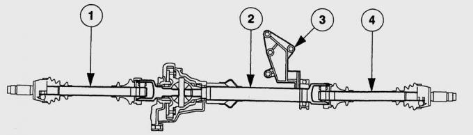
Fig. 12.12. Wheel drive shafts: 1 – left drive shaft; 2 – intermediate shaft with support bearing; 3 – cast iron bracket; 4 – right drive shaft
Despite the fact that the Fiesta gearbox housing is installed offset from the longitudinal axis of the car, the length of both drive shafts is the same. The right drive shaft is connected to the output flange of the gearbox via an intermediate shaft (Fig. 12.12).
Synchronizing joint.
Constant velocity joints of the drive shafts transmit torque evenly with any movement of the rear suspension. They contain balls that roll along a special spherical raceway depending on the movement of the front suspension. This ensures uniform drive of the front wheels regardless of the deviation of the drive shaft together with the suspension. Constant velocity joints have virtually no effect on the steering wheel. In the Fiesta, a removable joint is installed on the gearbox side of the drive shafts, and on the wheel side, the joint is rigidly fixed to the drive shaft.
Wheel hub.
The front wheel hub is mounted in the steering knuckle on two ball bearings. The outer joints of the drive shafts are attached with splines to the front wheel hubs. In the gearbox housing, the drive shafts are attached with splined connections to the differential axle gears. The play between the gearbox and the drive shaft is eliminated by the arrangement of the splines. The splines in the gearbox are located straight, the splines on the shaft are made at a slight angle. Different spline designs provide a connection with a preliminary tension, i.e. a fixed fit, eliminating all adjustments.

PRACTICAL TIPS
Drive shaft noise
Usually there are no problems with drive shafts, but their service life depends on the driving style of the car. Frequent sharp acceleration of the car with wheel slippage with the front wheels fully turned leads to intensive wear of the shafts.
Constant velocity joints of drive shafts may make noises that disappear and then reappear. Silent operation may even last for several days.
Characteristic noises, which are rhythmic beatings or crunching when pressing the accelerator pedal and coasting (may change when turning the steering wheel), indicate a malfunction in the joint on the wheel side.
This also applies to the steering wheel vibrating when turning a corner.
Clicking noises when starting off with the wheels turned may indicate a faulty drive shaft.
WARNING
Often similar symptoms indicate faulty wheel bearings.
[The original version can be found on the website fordbook]