Contents: Precautions when working with ECU ↳ Checking the resistance of the… ↳ Checking the resistance of the… ↳
In case of ignition system malfunction, check all electrical connections, tightening of threaded connections, technical condition of system elements. Check for 12 V voltage on both coils. With this circuit, connect the "+" of the voltmeter to the red wire of the coil, "-" to the "ground". Turn on the ignition and read the voltmeter. Check the second ignition coil in the same way. If there is no voltage, check the ignition relay fuse, as well as the coil connectors and wires.
NOTE: Before checking the integrity of the wires, disconnect the ignition system control unit.
Make sure that the connectors are connected to the coils correctly: the black connector to the coil of cylinders 1 and 4, the red connector to the coil of cylinders 2 and 3.
Precautions when working with ECU
It is prohibited to check the resistance of the ECU, since the supplied test voltage can disable the ECU. Disconnect the ECU connector before checking for a break in the ignition system wires.
Checking the resistance of the primary winding of the ignition coil
Check the technical condition of the coil connector. Connect an ohmmeter between the coil terminals (Fig. 7.54).
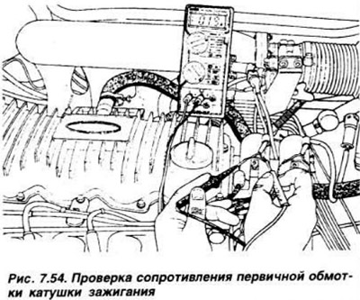
The device should show no more than 1.6 kOhm. Check the second ignition coil.
Checking the resistance of the secondary winding of the ignition coil
Disconnect the high-voltage wires from the spark plugs. Connect an ohmmeter between the high-voltage terminals of the coil (Fig. 7.55).
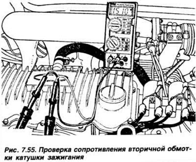
The device should show 15 kOhm +10%. Check the second ignition coil.
CHECKING THE IGNITION COIL INSULATION
Connect an ohmmeter between the plastic body of the coil and the ground. If the resistance value is below 1 MOhm, replace the coil. To check the power supply of the ECU, remove its connector block and connect the "+" tip of the device to terminal "3" of the ECU block, and the "-" tip to terminal "1" (Fig. 7.56).
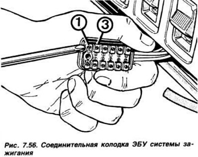
Turn on the ignition and make sure that the device shows 12 V. Otherwise, check the ignition timing setting.