Ignition and fuel injection systems (1.3 CFI engines before 1995)
Open large image in new tab »
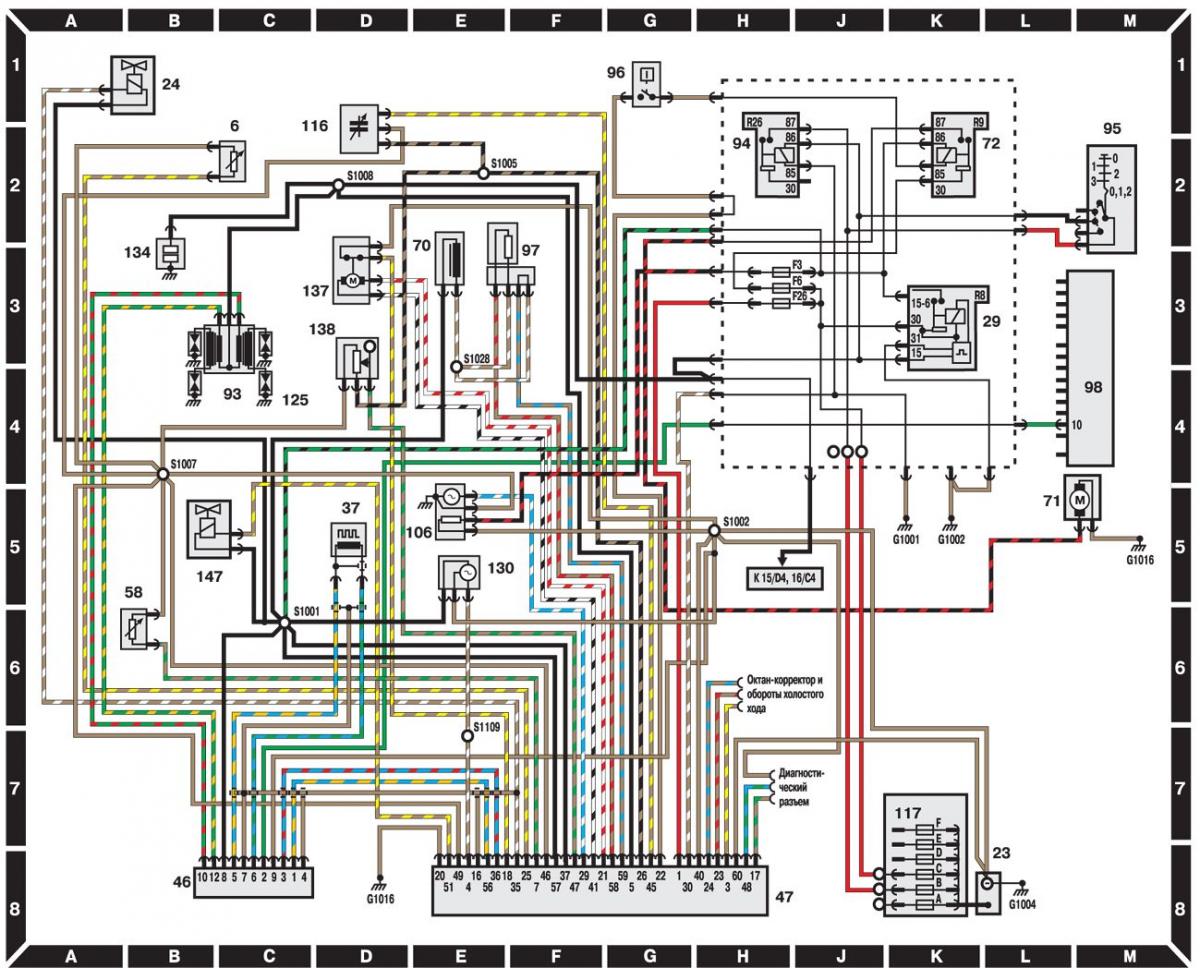
- 6 – intake manifold air temperature sensor;
- 23 – battery;
- 24 – electromagnetic valve;
- 29 – CFI fuel injection system power supply relay;
- 37 – crankshaft angle sensor;
- 46 – EDIS ignition control unit;
- 47 – EEC IV fuel injection control unit;
- 58 – coolant temperature sensor;
- 70 – fuel injector;
- 71 – fuel pump;
- 72 – fuel pump relay;
- 93 – ignition coil;
- 94 – ignition system power relay;
- 95 – ignition switch;
- 96 – switch;
- 97 – resistor;
- 98 – instrument cluster;
- 105 – oxygen sensor;
- 117 – Engine compartment fuse box;
- 125 – spark plug;
- 130 – vehicle speed sensor;
- 134 – capacitor;
- 137 – Throttle control motor;
- 138 – Throttle position sensor;
- 147 – electromagnetic air valve of the idle speed system
General description and symbols on electrical diagrams are located here →
The text was obtained in its entirety from the specified website FORDBOOK.RU