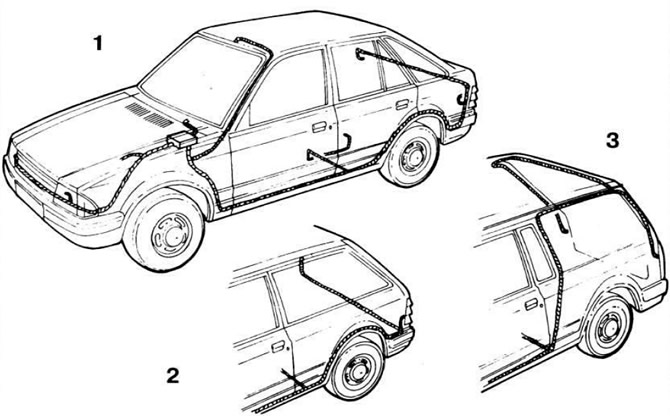
 Pic. 7.1. Location of car wiring harnesses «Escort».
1 - hatchback; 2 - station wagon; 3 - cargo-passenger version.
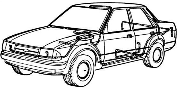 Pic. 7.2. Location of car wiring harnesses «Orion».
Most of the harnesses are connected to a mounting block located in the engine compartment on the mudguard of the left front wheel (pic. 7.3), where most of the fuses are (pic. 7.4) and auxiliary relays (pic. 7.5).
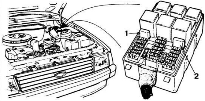 Pic. 7.3. Installation location of the vehicle mounting block «Orion» and location of fuses and relays.
1 - automatic switch of the central blocking of doors; 2 - automatic window switch.
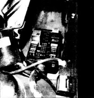 Pic. 7.4. The location of the fuses in the mounting block of the car «Escort».
left row - fuses Pr1-Pr5
middle row - Pr6-Pr11.
right row - Pr12-Pr16.
Thermal switches in a metal case are located behind the fuses of the outer rows.
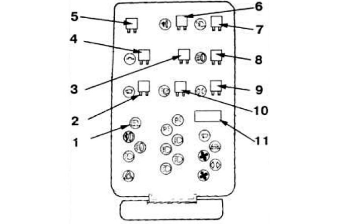 Pic. 7.5. The location of the relay in the mounting block of the car «Escort».
1 - automatic thermal switch for power windows; 2 — the relay of inclusion of a screen wiper; 3 - reserve; 4 - relay for switching on circuits connected to the ignition switch; 5 - reserve; 6 - relay for turning on fog lights; 7 — the relay of inclusion of heating of back glass; 8 - relay for switching on the main beam of headlights; 9 - relay-breaker of direction indicators; 10 - relay for switching on headlight washers; 11 - automatic thermal switch for central door locking.
Before replacing a blown fuse. it is necessary to eliminate the cause of its combustion by checking the circuits it protects according to table 7.1.
In addition to the designation on the cover of the mounting block with the same symbols as on the instrument panel, the fuses differ in color: red - 10 A, blue - 15 A, yellow - 20 A, white - 25 A; The rated current is indicated on the fuse itself.
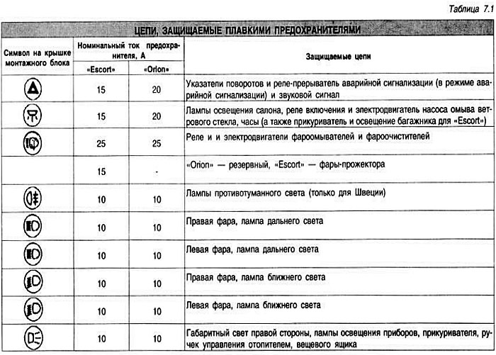
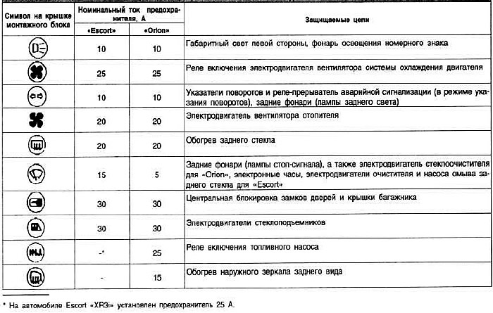
Wiring diagrams for electrical equipment
Electrical diagrams have a single numbering for all car models «Escort» and a slightly different numbering of the electrical circuits of the car «Orion». The first block of nine schemes refers to cars «Escort» release 1980-1982, the next block of eight schemes refers to cars «Escort» release 1983-1985 and the third block of ten schemes - to the car «Orion».
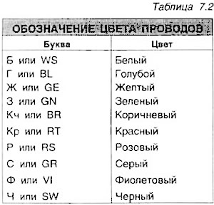
In all diagrams, the color of the wires is indicated by letters, with the first letter being the color of the wire itself, and the second letter being the color of the strip on the wire.
Connection points on «mass» marked with a letter «T» and a number indicating the connection point: 1 - left windshield pillar; 2 - body point near the left headlight; 3 - body point near the right headlight; 4 — a point of a body near a back left lantern; 5 — a point of a body near a back right lantern; 6 — an arm of the electric motor of a screen wiper; 7 - front part of the roof; 8 - left rear pillar; 9 - back of the roof.
Visitor comments