Removal
1. When the engine and transmission are separated from each other, allowing access to the clutch, special attention must be paid to the clutch release mechanism components located in the clutch housing.
Transmission. Тип G
2. If you have removed the engine but left the transmission in the vehicle, disconnect the clutch cable from the transmission release fork.
3. Unscrew the retaining bolts and separate the clutch housing from the transmission.
4. Separate the release fork from the pivot shaft by pulling it to the side, then remove the lever and thrust bearing.
5. Remove the retaining ring and separate the thrust bearing from the release fork.
Transmission. Type N and MT75
6. Separate the thrust bearing from the release fork and remove it from the guide sleeve (see Figure 5.6).
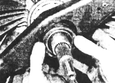
Figure 5.6. Remove the thrust bearing by separating it from the clutch release lever.
7. Pull the release fork to the side, unhook it from the steering axle and remove it by moving it towards you along the transmission input shaft (see Figure 5.7).
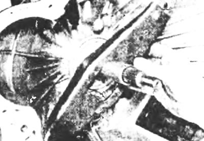
Figure 5.7. Remove the clutch release lever by sliding it away from the pivot shaft.
Inspection
8. Check the bearing for smooth sliding and replace it with a new one if any sign of roughness or harshness is found. Do not attempt to disassemble, clean or lubricate the bearing.
9. As mentioned earlier, it is worth replacing the thrust bearing with a new one if its condition is questionable.
10. Check the condition of the release fork, making sure that it is not deformed.
Installation
All types of transmission
11. Installation is carried out in the reverse order of removal. Apply a thin layer of high melting point lubricant to the thrust bearing guide bushing and the release fork pivot shaft, make sure the bearing is properly installed in the release lever (and is secured with a retaining ring on the G-type gearbox) and that the forked end of the release fork is fixed to the pivot axle (see illustration). On a G-type transmission, install the clutch housing and tighten the retaining bolts to specification (see Figure 5.11).
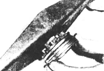
Figure 5.11. Correct positioning of the thrust bearing on the release fork.