Note: This description describes brush replacement for Lucas/Magneti-Marelli M127 starters. However, the procedures for other starter types are similar. Please refer to the detailed view of the corresponding starter to clarify the differences between the types (see Figure 9.0, a-d).
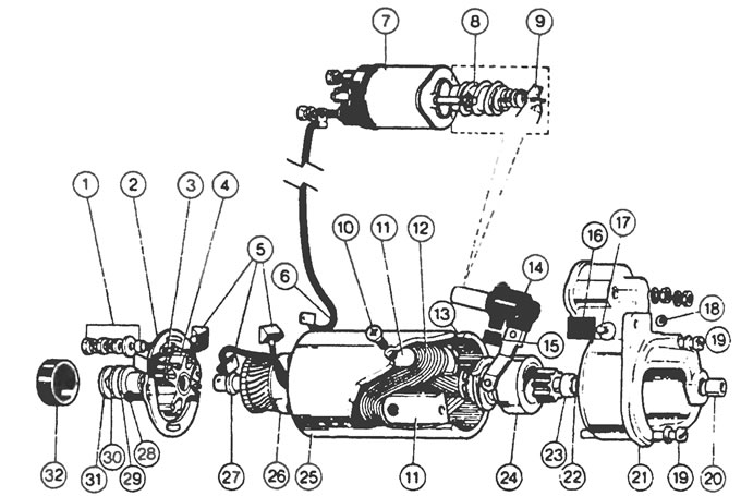
Figure 9.0a. Detailed view of the Lucas/Magnet! Marelli 5M90 starter 1. Clamp nuts and washers, 2. Commutator end cover, 3. Brush holder, 4. Brush springs, 5. Brushes, 6. Solenoid wire, 7. Solenoid relay, 8. Return spring, 9. Pinion engagement lever, 10. Pole shoe screw, 11. Pole shoe. 12. Series coil of field winding, 13. Connection of field winding to ground, 14. Rubber seal, 15. Sealing plug, 16. Dust cover, 17. Support pin, 18. Retaining clamp, 19. Drive cover clamp bolt, 20. Armature shaft sleeve, 21. Starter drive cover, 22. Armature shaft retaining ring, 23. Thrust ring, 24. Drive, 25. Starter housing, 26. Armature, 27. Thrust washer, 28. Commutator cover bolt, 29. Armature shaft sleeve, 30. Thrust washer, 31. Washer with internal teeth, 32. Dust cover.
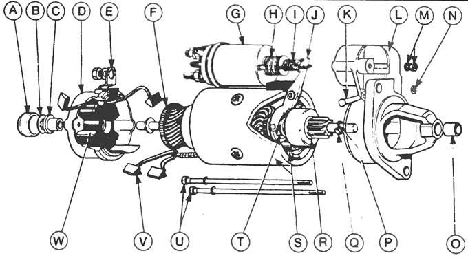
Figure 9.0, b. Detailed view of the Lucas / Magnet! Marelli 2M100 starter: A - Rubber cover, B - Lock, C - Armature shaft sleeve, D - Commutator end cover, E - Contact terminal, F - Armature, G - Solenoid relay, H - Return spring, I - Damping spring, J - Drive engagement lever, K - Support pin, L - Bracket, M - Solenoid relay nut and washer, N - Support pin clamp, O - Armature shaft sleeve, P - Armature shaft lock washer, Q - Thrust ring, R - Drive pinion, S - Starter housing and pole shoe, T - Buffer spring, U - Tie bolts, V - Brush, W - Brush holder
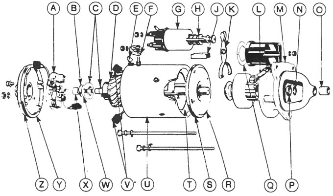
Figure 9.0, c. Detailed view of the Lucas/Magneti-Marelli M127 starter: A - Brush holder, B - Washer, C - Brake shoes, D - Armature, E - Flexible link, F - Copper link, G - Solenoid relay, H - Return spring, J - Seal, K - Drive release lever, L - Support pin, M - Starter drive cover, N - Armature shaft lock washer, O - Armature shaft sleeve, P - Thrust ring, Q - Gasket, R - Partition, S - Sealing ring, T - Field winding coil, U - Starter housing, V - Field winding brushes, W - Steel washer, X - Armature shaft sleeve, Y - Sealing ring, Z - Commutator end cover
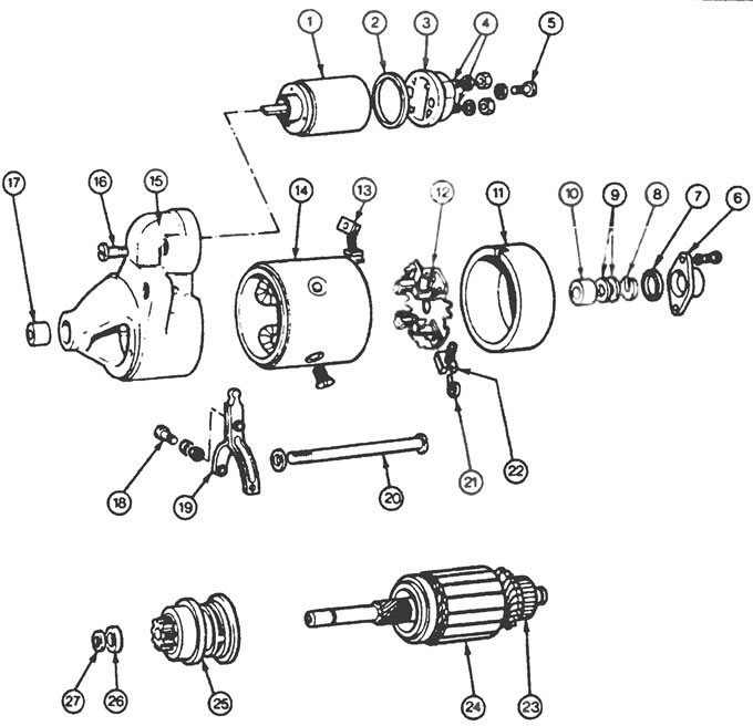
Figure 9.0, d. Detailed view of the Bosch long frame starter: 1. Solenoid relay, 2. Gasket. 3. Contacts. 4. Terminals, 5. Fixing bolt, 6. Shaft end cover. 7. Seal, 8. Armature shaft thrust washer, 9. Washers, 10. Armature shaft sleeve, 11. Commutator end cover, 12. Brush holder, 13. Connecting wire, 14. Starter housing, 15. Starter drive cover, 16. Solenoid relay fixing bolt, 17. Armature shaft sleeve, 18. Support screw, 19. Drive engagement lever, 20. Tie bolt, 21. Brush spring, 22. Brush, 23. Commutator, 24. Armature core, 25. Drive pinion, 26. Thrust washer, 27. Lock washer.
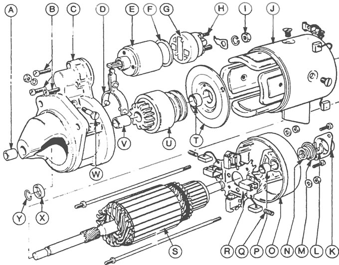
Figure 9.0, d. Detailed view of the Bosch JF starter (2.7 kW): A - Bearing, B - Solenoid Relay Bolts, C - Drive Cover, D - Pinion Activation Lever, E - Solenoid Relay, F - Gasket, G - Contact Holder, H - Terminals, I - Nut, J - Starter Housing, K - Rear Cover, L - Thrust Washer, M - Seal, N - Washers, O - Commutator Rear Cover, P - Armature Shaft Bushing, Q - Brush Spring, R - Brush Holder, S - Armature, T - Middle Bearing, U - Drive Pinion, V - Armature Shaft Bushing, W - Support Screw, X - Lock Washer, Y - Shaft Thrust Washer.
1. Remove the starter from the vehicle as described in the previous Section.
2. Remove the two small bolts and a pair of large tie bolts from the switch end cover (see Figure 9.2).
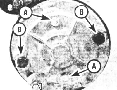
Figure 9.2. Remove the two small screws (A) and a pair of tie bolts (B) from the rear manifold cover
3. Separate the rear cover of the collector from the starter (see Figure 9.3).
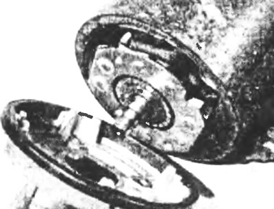
Figure 9.3. Unscrew the rear cover of the manifold from the starter
4. Remove the brake pads, anchors and springs and two washers from the rear cover (see figure 9.4,a,b).
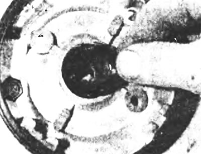
Figure 9.4,a. Remove the brake pads with springs...
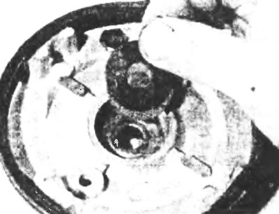
Figure 9.4, b.... and two washers from the recess in the back cover.
5. Remove the field winding brushes from their clamps and separate the brush holder from the commutator (see Figure 9.5). Remove the two remaining brushes from the brush holder after removing it.
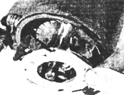
Figure 9.5. Separate the brush holder from the commutator.
6. Check the length of the brushes. If any of them are worn to the minimum length given in the Specifications, replace them with new ones (see Figure 9.6).
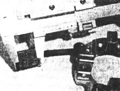
Figure 9.6. Check the length of the brushes and replace them if necessary.
7. To replace the field winding brushes, cut the brush lead as close to the supply conductor as possible and remove the old brush. Strip the conductor to make room for soldering and solder the new brush lead. Also replace the second brush of the excitation winding.
8. To replace the brushes of the brush holder, move the soldering iron to the place where the brushes are soldered. Once the solder has melted, open the connector, remove the old brush lead and insert the new one. Close the connector and solder it.
9. Clean the commutator with fine sandpaper, then wipe clean with a cloth slightly dampened with solvent.
10. Check the condition of the anchor brake shoe pin. If it is damaged or worn, remove it along with the pin and install a new pin (see Figure 9.10).
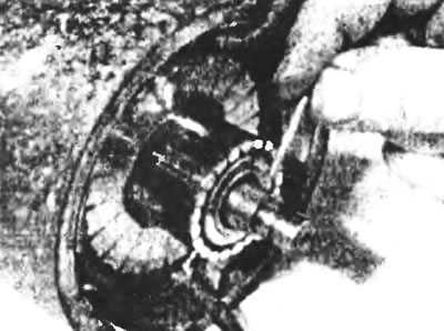
Figure 9.10. Replace the brake shoe pin if it is damaged or worn.
11. Check that all four brushes move freely in their clamps and that the springs are not damaged and provide equal pressure.
12. Insert the two brushes of the brush holder into their clamps and hook the springs opposite the brushes (see Figure 9.12). Do not insert all the brushes at once, otherwise it will be difficult to install the brush plate onto the commutator.
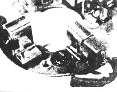
Figure 9.12. Place the two brushes of the brush holder in their clamps and engage the springs.
13. Insert the two field winding brushes into their clamps in the same way as when installing the brush holder on the commutator. Once the brushes are in place, push the ends of the brushes toward the commutator until the springs slide into place at the ends of the brushes.
14. Install the brake pads with springs and two washers on the rear cover.
(A copy of the article is available on the website: www.FordBook.ru)