| Engine 1.1 | |
| Group I | 68.65...68.66 mm |
| II group | 68.66...68.67 mm |
| Group III | 68.67...68.68 mm |
| Piston clearance in cylinder | 0.015...0.050 mm |
| Engine 1.4i | |
| Group I | 77.19...77.20 mm |
| II group | 77.20...77.21 mm |
| Group III | 77.21...77.22 mm |
| IV group | 71.22...77.23 mm |
| Piston clearance in cylinder | 0.020...0.045 mm |
| Engine 1.6i | |
| Group I | 79.91...79.92 mm |
| II group | 79.92...79.93 mm |
| Group III | 79.93...79.94 mm |
| IV group | 79.94...79.95 mm |
| Piston clearance in cylinder | 0.010...0.040 mm |
| Diesel engine 1.8 | |
| Group A | 82.46...82.47 mm |
| Group B | 82.47...82.48 mm |
| Group C | 82.49...82.50 mm |
| Group D | 82.51...82.52 mm |
| Piston clearance in cylinder | 0.020...0.055 mm |
| Permissible amount of piston protrusion from the cylinder | 0.500...0.840 mm |
The wear limit is 0.15 mm of the total gap formed as a result of wear of the piston and cylinder liner.
Burn marks on the bottoms or obvious wear marks on the piston skirts indicate the need to replace the entire piston set. Replacement of the piston set is also necessary when only one piston is damaged. In diesel engines, the pistons can be separated from the connecting rods after removing the expansion retaining rings. In 1.1 and 1.4i engines, the piston pins are installed in the pistons with tension. If necessary, they can only be removed under a press. After this operation, the pistons are no longer suitable for use, they cannot be reinstalled and must be replaced as a set.
Installation of pistons with connecting rods can only be performed by professionals, as this is a technically very complex task and requires special tools to complete it.
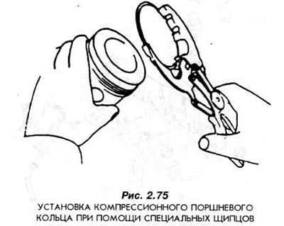
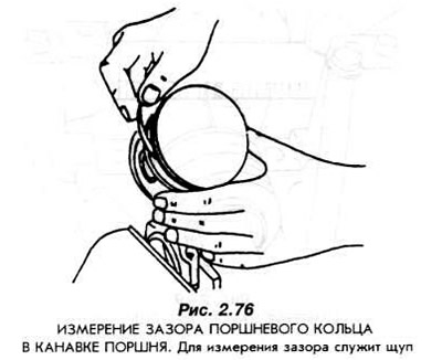
The piston rings must be inserted into the corresponding piston grooves and the clearances measured with a feeler gauge (Fig. 2.76). Inserting the piston rings into the cylinder bores one by one, measure the clearances in the locks with a feeler gauge. The permissible values of these clearances are given in Section 1.1. If the clearance of the piston ring lock is greater than the permissible value, it is necessary to repeat the measurement using a new piston ring. If it turns out that in this case the clearance is also too large, this means that the cylinder liner is worn. In this case, it is necessary to bore the engine cylinder liners to the next repair size and use new pistons of an increased size. If the clearances in the ring locks turn out to be too small, saw the locks to the required clearance values. To do this, secure a flat file in a vice and saw the ring lock, moving both of its surfaces simultaneously on both sides of the file. Use special pliers to install the rings on the pistons. The "TOR" marking on the rings must be visible from above.
The pistons are mounted with the connecting rods in such a way that the arrows located on the piston bottoms are directed towards the valve timing drive transmission.