Contents: Heater. Models before 1995 ↳ Stop ↳ Models since 1995 ↳ Heater radiator, fan motor and… ↳ Heater radiator, fan motor and… ↳
Heater. Models before 1995
Removal
1. Disconnect the negative battery cable.
2. Drain the coolant from the cooling system as described in Chapter 1.
3. Loosen the retaining clamps and separate the heater inlet and return pipes from the bulkhead (see Figure 10.3).
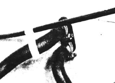
Figure 10.3. Loosen the retaining clamps and separate the heater inlet and return pipes.
4. Inside the cabin, unscrew the fixing screws and remove the heating control panel. When removing it, separate the electrical plugs and indicator sockets from the fan switch and cigarette lighter (see Figure 10.4). Remove the ashtray.
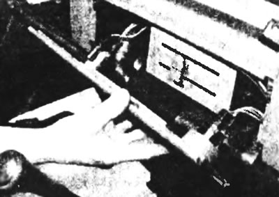
Figure 10.4. Unscrew the four fixing screws and remove the heating control panel
5. Disconnect the heater flap control panel by unscrewing the two lock nuts, one on each side (see figure 10.5a, b).
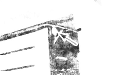
Figure 10.5a. Disconnect the heater flap control panel by unscrewing the two lock nuts...
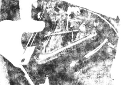
Figure 10.5b....then remove the panel.
6. Separate the windshield heater and ventilation pipes (see Figure 10.6).
Figure 10.6. Disconnect the windshield heating and ventilation pipes.
7. Unscrew and remove the four screws securing the heater to the bulkhead and carefully remove the heater from the vehicle. When removing, disconnect the fan motor wiring.
Stop
8. The installation procedure is the reverse of the removal procedure, but note the following points:
a) When installing the heater flap control panel, place the control levers 2 mm from their stops and secure the control cable with a clamp. Each valve must be moved to its extreme position;
b) Make sure that the electrical wiring plugs of the fan motor and cigarette lighter are securely fastened;
c) After checking the reliability of the heater pipes connection, fill the cooling system with liquid again, as described in Chapter 1;
d) After starting the engine, turn on the heater and ventilation system for a few minutes to check their operation, as well as the possibility of coolant leaks from the system.
Models since 1995
Removal
9. Disconnect the negative battery cable.
10. Drain the cooling system as described in Chapter 1.
11. From inside the engine compartment, disconnect the connections and disconnect the heater hoses from the radiator (see Fig. 10.11). To do this, squeeze the flange of the plastic insert and remove the hoses using angle-nose pliers. Be careful not to lose the seals.
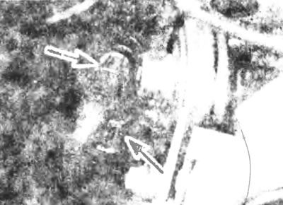
Figure 10.11. On later models, remove the connections (indicated by arrows) and disconnect the pipes.
12. Remove the panel (see section 29 of chapter 11).
13. Unscrew the four bolts securing the heater to the bulkhead (see Figure 10.13).
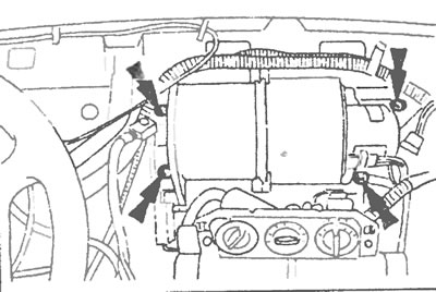
Figure 10.13. Unscrew the four bolts (indicated by arrows), fastening the heater to the partition.
14. Pull the heater forward and remove it.
Installation
15. Installation is carried out in the reverse order of removal.
Heater radiator, fan motor and exercise organs. Models before 1995
Disassembly
16. After removing the heater, separate the control cables from the heater, and remove the control cables and panel.
17. Unscrew the eight fixing screws and separate the upper part of the case from the lower part (see Figure 10.17).
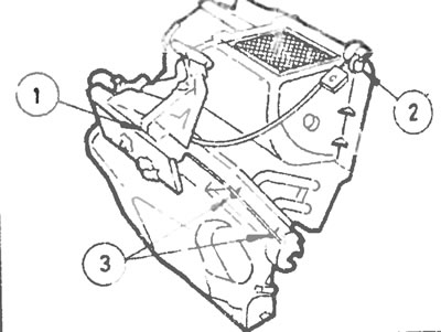
Figure 10.17. Heater: control unit (1), air damper assembly (2) and mounting bolts (3).
18. To remove the fan motor, unscrew the three screws and remove it from the housing (see Figure 10.18).
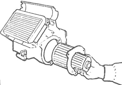
Fig. 10.18. Removing the fan motor.
19. Remove the coolant pipe support screw and foam seal. Remove the seal and carefully remove the radiator from the heater housing (see Figure 10.19).
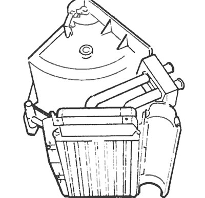
Figure 10.19. Carefully pull out the radiator.
20. Further dismantling of the heater is unlikely to be necessary, but if necessary, this can be done by releasing the clamps.
21. Replace defective components with new ones as necessary. Restoring most of them is either impossible or impractical.
Assembly
22. Assemble the parts in the reverse order of disassembly. If the flap valve toothed sector has been removed, install it, then place the actuator and align the protrusions of the sleeve shaft with the grooves of the casing by rotating, (lightly to secure them properly) (see Figure 10.22).
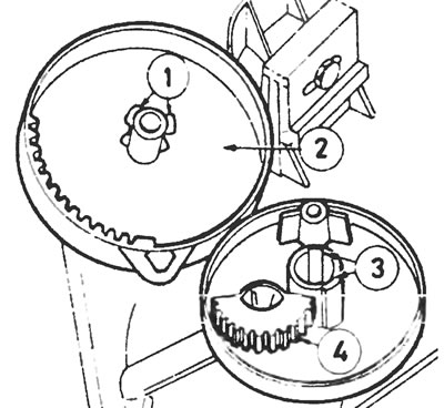
Figure 10.22. Air distribution damper assembly: 1 - centering roller tongues, 2 - drive disk, 3 - housing grooves, 4 - toothed sector.
23. When reassembling the housing halves, use new foam seal. Also install a new seal on the radiator when installing it.
Heater radiator, fan motor and controls. Models since 1995
Disassembly
24. After removing the heater, disconnect the fan motor mounting plug and separate the fan motor resistor from the heater housing side (see Figure 10.24).
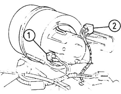
Figure 10.24. On later models, disconnect the power plug (1) and the motor resistor (2).
25. Disconnect the mounting multi-pin plug from the air recirculation flap control motor (see Figure 10.25).
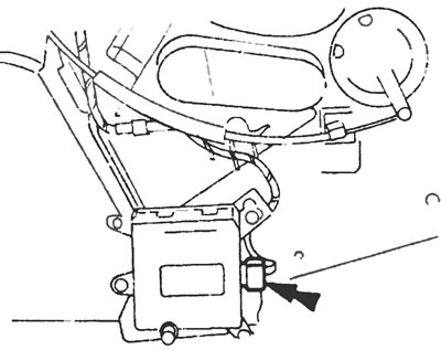
Figure 10.25. Disconnect the plug (indicated by the arrow) from the recirculation flap electric motor.
26. Disconnect the external heating control unit cables from the housing by springing back the clamps. Disconnect the internal cables from the adjustment levers and remove the control unit.
27. While holding the fan motor retaining key, turn the motor counterclockwise and separate it from the housing.
28. Unscrew the three screws (see Figure 10.28) and remove the panel covering the radiator. Carefully pull it out of the heater housing.
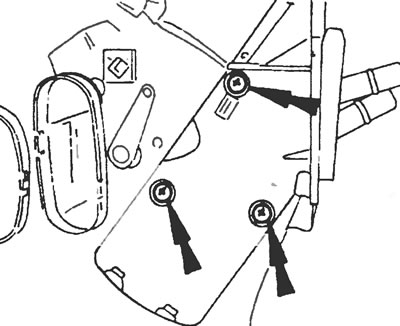
Figure 10.28. Remove the three radiator panel screws (indicated by arrows).
29. Unscrew the three screws and remove the air recirculation valve control motor.
Assembly
30. Produced in reverse order.