Contents: Models before 1995 ↳ Models after 1995 ↳
1. Remove the instrument cluster as described in the previous section. When working with the instrument panel, as well as when removing or installing its elements, try not to damage the printed circuit board. Do not drop the instrument cluster or impact the printed circuit board, as this may cause damage.
Models before 1995
Indicator lights and backlighting lights
2. Unscrew the bulb socket and remove it from the back of the panel. Remove the light bulb from the socket (see Figure 6.2).
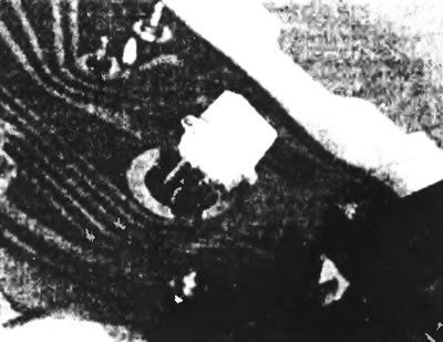
Figure 6.2. Removing the bulb holder from the instrument panel.
3. Install in the reverse order of removal.
Instrument panel glass
4. After unscrewing the two fixing screws at the top and disconnecting the two fasteners at the bottom of the shield, remove the glass (see figure 6.4).
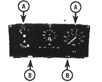
Figure 6.4. Upper (A) and lower instrument panel glass fasteners (B).
5. Install in the reverse order of removal.
Speedometer
6. Unscrew the six fixing screws and separate the front part of the instrument panel from the main unit (see figure 6.6).
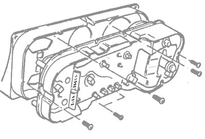
Figure 6.6. Remove the six screws to separate the front portion of the instrument cluster from the main unit.
7. Remove the speedometer from the instrument cluster by unscrewing the two fixing screws (see Figure 6.7).
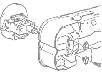
Figure 6.7. Removing the speedometer.
8. Install in the reverse order of removal.
Fuel level indicator
9. After unscrewing the six fixing screws, separate the front part of the instrument panel from the main unit.
10. After unscrewing the four fixing nuts, remove the washers. Remove the fuel gauge from the instrument cluster on the front side (see Figure 6.10).
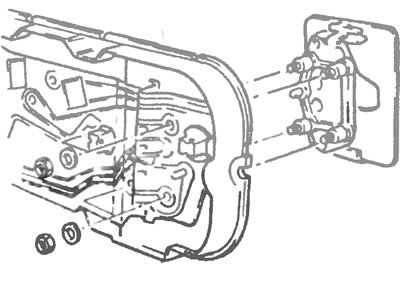
Figure 6.10. Removing the fuel level gauge.
11. Install in the reverse order of removal.
Watch
12. Unscrew the six retaining screws and separate the front part of the instrument panel from the main unit.
13. After unscrewing the three lock nuts, remove the clock mechanism from the main unit.
14. Install in the reverse order of removal.
PCB
15. Remove the lamp holders, clock and fuel gauge.
16. Disconnect the multi-pin connector block and carefully remove the printed circuit board (see Figure 6.16).
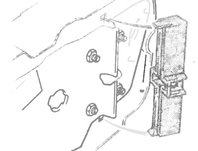
Figure 6.16. Disconnect the multi-pin connector block and carefully remove the printed circuit board.
17. Install in the reverse order of removal.
Models after 1995
Control and illuminating lamps
18. Unscrew the socket of the light bulb you are interested in and pull it out of the instrument panel from the back side. Remove the light bulb from the socket.
19. Install in the reverse order of removal.
Instrument panel glass
20. Carefully release the five retaining tabs and remove the glass from the frame.
21. Mark the installation location of the symbolic nozzles and remove them from the front of the main unit.
22. Install in the reverse order of removal.
Speedometer
23. Remove the instrument panel glass, unscrew the three screws and remove the speedometer from the panel.
24. Install in the reverse order of removal
Tachometer
25. After removing the instrument panel glass, unscrew the only screw and pull the tachometer out of the main unit.
26. Install in the reverse order of removal.
Fuel level and temperature indicators
27. After removing the instrument panel glass, unscrew the single screw securing each of the indicators. Pull the pointer you are interested in from the main block.
28. Install in the reverse order of removal.
PCB
29. Remove the bulb holders, instruments and indicators as described above.
30. Remove the needle contacts of the indicators and instruments from the printed circuit board.
31. Using a thin, flat-spouted punch (core), push the pins in to release the stranded connector retainers, and remove the connectors.
32. Carefully lift the printed circuit board off the pins and remove it from the rear of the instrument cluster.
33. Install in the reverse order of removal.
For more information, please visit the specified website [FORDBOOK.RU]