Contents: Multi-function steering column… ↳ Ignition and starter switch (lock)… ↳ Interior light switch ↳ Switches located on the instrument… ↳ Switches located on the side of the… ↳ Brake light switch ↳ Heating switch ↳ Electric window switch ↳
Multi-function steering column switches
1. The steering column has two multi-function switches. The left switch contains the full beam and flashing headlight switch, horn switch, turn signal switch and hazard signal switch; on the right switch are located the switches for the light, windshield wiper and washer. Both switches can be removed and reinstalled independently of each other as follows.
2. Disconnect the negative battery cable.
3. Unscrew the screws and remove the upper and lower steering column covers (see figure 4.3,a,b).
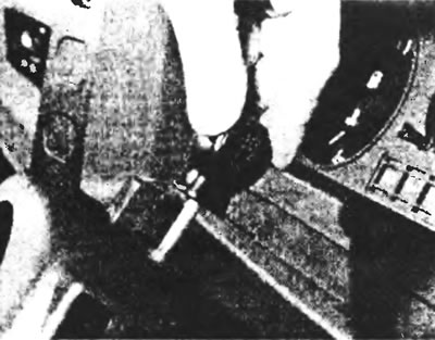
Figure 4.3,a. After unscrewing the upper fixing screw...
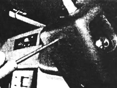
Figure 4.3,b....and the lower retaining screws, remove both steering column covers.
4. Remove the two Phillips screws to separate the left or right switch from the steering column (see figure 4.4).
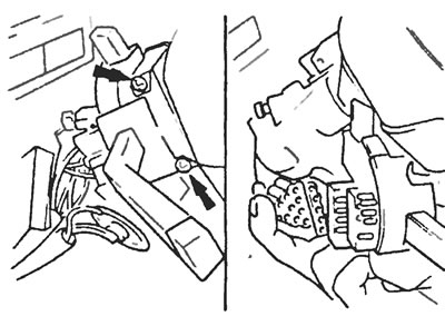
Figure 4.4. Unscrew the two screws (indicated by arrows), remove the multi-function switch and disconnect the multi-pin wiring plug.
5. Disconnect the multi-pin plug and remove the switch you are interested in.
6. Install in the reverse order of removal.
Ignition and starter switch (lock) with cylinder
7. Disconnect the negative battery cable.
8. Unscrew the screws and remove the upper and lower steering column covers.
9. After inserting the ignition key, turn it to position "1". Release the lock spring by inserting a suitable rod or special tool through the inspection hole on the side of the cylinder and pull out the steering column lock cylinder (see figure 4.9) Align the cam with a light movement of the key
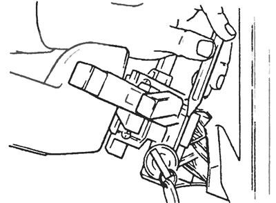
Figure 4.9. Release the lock spring by inserting a suitable rod through the inspection hole in the side of the cylinder.
10. With the key fully inserted, remove the spring clip (be careful not to damage its location), then pull the key out approximately 5 mm and remove the cylinder from the holder.
11. Disconnect the multi-pin plug and unscrew the two screws (headless with a slot for a screwdriver) then pull out the ignition switch socket (see Figure 4.11).
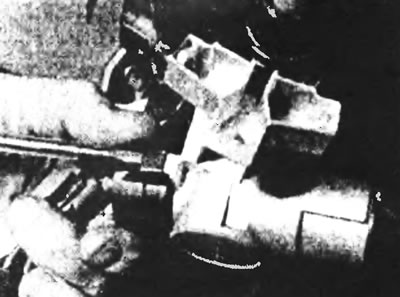
Figure 4.11. Remove the ignition switch socket by unscrewing the two screws.
12. Install in the reverse order of removal. Check the operation of the ignition switch and starter in all switch positions.
Interior light switch
13. Disconnect the negative battery cable.
14. Open the door and unscrew the Phillips screw from the door post (see Figure 4.14).
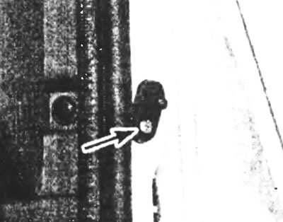
Figure 4.14. Interior light switch mounting screw (indicated by the arrow).
15. After removing the switch from the door post, pull the wire, preventing it from returning back to the post. If necessary, tie it to the door post while you remove the switch.
16. Disconnect the wire and remove the switch.
17. Install in the reverse order of removal.
Switches located on the instrument panel
Models before 1995
18. Disconnect the negative battery cable.
19. Unscrew the retaining screws and remove the upper and lower steering column covers
20. Loosen the upper steering crown mounting nuts to lower it slightly, then unscrew the screws securing the instrument panel frame, tilt it and pull it out (see figure 4.20,a,b).
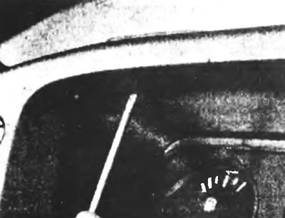
Figure 4.20,a. Unscrew the screws securing the instrument panel frame...
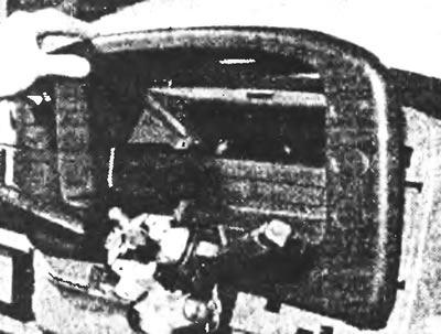
Figure 4.20, b....then tilt it and pull it out (the steering wheel has been removed for clarity).
21. After pushing the corresponding switch out of the panel, disconnect the wiring connector and remove the switch (see Figure 4.21).
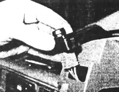
Figure 4.21. After pressing the corresponding switch out of the panel, disconnect the wiring connector and remove the switch.
22. Install in the reverse order of removal. Tighten the upper column mounting nuts to specification (see Chapter 10 Specifications).
Models since 1995
23. Disconnect the negative battery cable.
24. Unscrew the retaining screws and remove the upper and lower steering column covers.
25. Remove the left and right steering column multifunction switches as described earlier in this Section.
26. Unscrew the four screws securing the instrument cluster surround and remove it.
27. Remove the two screws securing the heating and ventilation control panel and remove the panel (see Figure 4.27).
28. Carefully pull the corresponding switch forward, disconnect the connector and remove the switch (see Figure 4.28).
29. Install in the reverse order of removal.
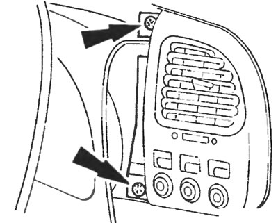
Figure 4.27. Remove the two screws securing the heating and ventilation control panel (indicated by arrows), and remove the panel.
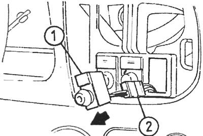
Figure 4.28. Carefully pull the corresponding switch (1) forward, disconnect the connector (2) and remove the switch.
Switches located on the side of the instrument panel
Models since 1995
30. Disconnect the negative battery cable.
31. Using a small screwdriver, carefully pry up the bottom of the switch on the side of the front panel (see Figure 4.31). Once the switch is released, remove it and disconnect the contact connector.
32. Install in the reverse order of removal.
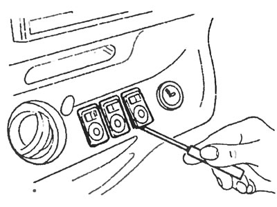
Figure 4.31. Using a small screwdriver, carefully pry up the bottom of the switch on the side of the instrument panel and remove it.
Brake light switch
33. Disconnect the wiring connector from the switch, then unscrew the switch counterclockwise and remove it from the retaining bracket (see Figure 4.33).
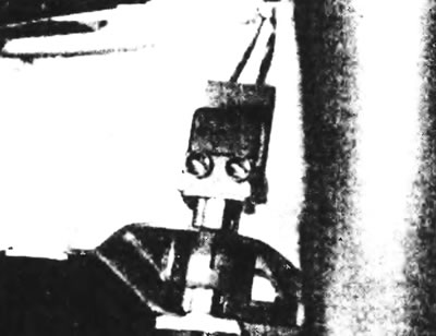
Figure 4.33. Location of the brake light switch on the pedal bracket.
34. To reinstall the switch, connect the wiring connector and insert the switch into the retaining bracket.
35. While holding the brake pedal stationary, push the switch in until it stops, then turn it clockwise until it snaps into place.
Heating switch
Models before 1995
36. Disconnect the negative battery cable.
37. After removing the four screws securing the heater control panel to the instrument panel, pull the panel out slightly to access the rear of the switch (see Figure 4.37).
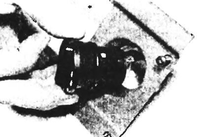
Figure 4.37. Removing the control panel.
38. After disconnecting the switch plug, squeeze the tabs of the lock and pull the switch out of the panel (see Figure 4.38).
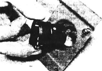
Figure 4.38. Squeeze the latch tabs and pull the switch out of the panel.
39. Install in the reverse order of removal.
Models since 1995
40. See section "Heating and Ventilation Components - Removal and Installation".
Electric window switch
41. Disconnect the negative battery cable.
42. Carefully pry the switch holder away from the door.
43. After disconnecting the multi-pin plug, pull the switch out of the holder by pressing on the side grips. If there are two switches installed in the holder, note the positions of the multi-pin plugs if you remove both switches.
44. Install in the reverse order of removal.