Models before 1995
Removal
1. Disconnect the negative battery cable.
2. Remove the steering wheel as described in Chapter 10.
3. Remove the steering column switches as described in Chapter 12.
4. Remove the instrument cluster or tachograph as described in Chapter 12.
5. After unscrewing the four screws securing the heater shield, disconnect the switch wiring connector from it and remove the shield.
6. After unscrewing the two fixing nuts, pull out the heating control panel. Separate the hot air supply hoses.
7. Release the two front panel latches located in the glove compartment by turning each one a quarter turn. Remove the four front panel retaining screws (two on each side), and then release the three fasteners along the top edge of the front panel by turning each one a quarter turn. Remove the panel (see Figure 29.7, a, b).
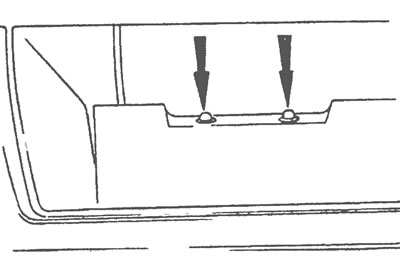
Figure 29.7,a. Release the two latches in the glove compartment by turning each one a quarter turn.
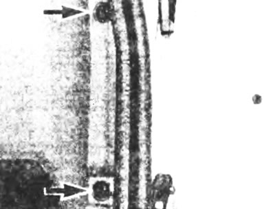
Figure 29.7b. Location of the side fixing screws of the front panel.
Installation
8. Installation is carried out in the reverse order of removal.
9. Refer to the relevant chapters as necessary for installation details of related components. Make sure all electrical connections are making good contact. Upon completion, check the operation of all switches, instruments and controls.
Models since 1995
Removal
10. Disconnect the negative battery cable.
11. Remove the front pillar trim as described in Section 30.
12. Remove the steering wheel as described in Chapter 10.
13. Remove the passenger side airbag as described in Chapter 12.
14. Remove the instrument panel and radio as described in Chapter 12.
15. Remove the screws and separate the upper and lower covers from the steering column.
16, Loosen the Phillips head screws and separate the multifunction switch assembly from the steering column.
17. Disconnect the multi-pin plug and remove the multi-function switch from the steering column.
18. Unscrew the two screws and separate the radio trim from the front panel.
19. Disconnect the multi-pin plug and remove the trim surrounding the radio.
20. Remove the two screws and the air conditioner switch panel located on the driver's side. Disconnect the multi-pin switch plugs and remove the panel.
21. Remove the remaining switches, hazard warning lights and cigarette lighter, if necessary, in accordance with the procedures described in Chapter 12.
22. Remove the two screws securing the heater control panel to the front panel (see Figure 29.22).
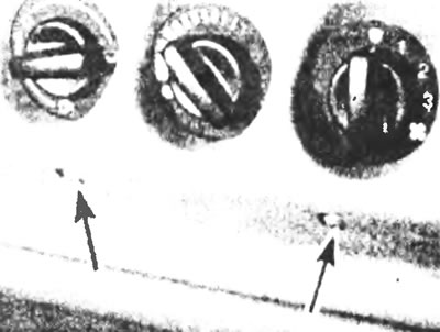
Figure 29.22. On later models, remove the two screws securing the heating control panel.
23. Unscrew the steering column bracket fixing nut.
24. Unscrew the fixing screw of the glove box support bracket (see Figure 29.24).
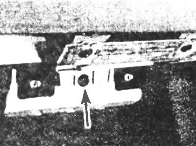
Figure 29.24. Unscrew the fixing screw (indicated by the arrow) supporting bracket for the glove compartment.
25. Pry up and remove the covers of the fixing screws, unscrew the screws running along the top edge of the panel (see figure 29.25).
Figure 29.25. Pry up and remove the screw covers and unscrew the screws running along the edge of the front panel.
26. Remove two screws on each side of the panel. To access the screws, pull out the front door seal in areas adjacent to the instrument panel.
27. With the help of an assistant, remove the panel from its location, if necessary, detach any ventilation deflectors, cables or plugs that interfere with the removal of the panel and remove the panel.
Installation
28. Install in the reverse order of removal. Please refer to the relevant chapters if necessary for further details on installing related components. Make sure all electrical connections are securely connected. Upon completion, check the operation of all switches, instruments and controls.
(The original version can be found on the website fordbook.ru)