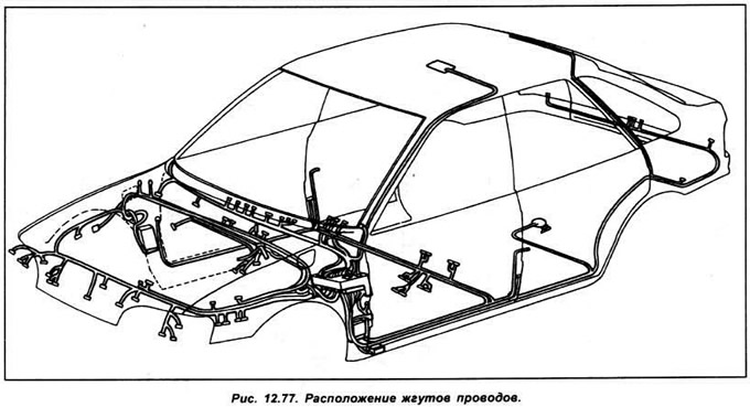
2. The diagrams correspond to the top view of the vehicle.
3. Wires that are connected between diagrams are marked with references to the diagram and grid cell, for example, 2/A1 denotes the position of A1 on the grid of diagram 2.
4. Complex products are shown in diagrams as blocks and internal connections are shown separately.
5. Positive voltage wires are red and all ground wires are brown.
6. Not all electrical components are available on all models.
Fuses
| Fuse | Current | Protected circuit |
| 1 | 30A | Heated rear window and exterior mirrors |
| 2 | 30A | Anti-lock braking system |
| 3 | 10A | Oxygen sensor |
| 4 | 15A | Right high beam |
| 5 | 20A | Fuel pump |
| 6 | 10A | Right side light |
| 7 | 10A | Left side light |
| 8 | 10A | Rear fog light |
| 9 | 30A | Radiator fan |
| 10 | 10A | Left auxiliary sowing |
| 11 | 15A | Front fog light |
| 12 | 10A | Direction indicator, reversing lights |
| 13 | 20A | Windscreen wiper motor, washer pump |
| 14 | 20A | Heater fan |
| 15 | 30A | Anti-lock braking system |
| 16 | FOR | Heated windshield |
| 17 | FOR | Heated Windshield Relay |
| 18 | 15A | Left far sows |
| 19 | 20A | Central locking system, anti-theft device |
| 20 | 15A | Sound signal |
| 21 | 15A | Interior lighting, clock, radio, cigarette lighter |
| 22 | 30A | Glass with electric window lift |
| 24 | 10A | Right auxiliary sowing |
| 25 | 3A | Engine Management System EEC IV |
| 27 | 10 | Stop - brake lights |
Additional fuses (in engine compartment)
| Fuse | Current | Protected circuit |
| A | 80A | Power cables to the main fuse box |
| IN | 60A | Power cables to the main fuse box |
| WITH | 60A | Power cables to the main fuse box |
| D | 50A | Cooling fan |
| E | 50A | Heated windshield and rear window |
| F | 50A | Glow plug (diesel) |
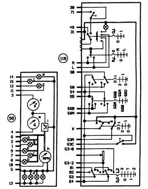
Instrument cluster
- a - battery charging indicator light
- b - handbrake indicator light
- c - high beam indicator lamp
- d - instrument cluster illumination
- e - fuel level indicator
- f - temperature indicator
- d - oil pressure indicator lamp
- h - tachometer
- i - voltage stabilizer
- j - ABS warning light
- k - dampers
- l - left turn indicator lamp
- m - right turn indicator lamp
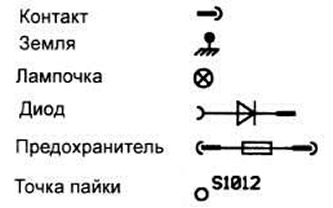
Designations on diagrams
The original can be found on the specified resource: www.fordbook.ru