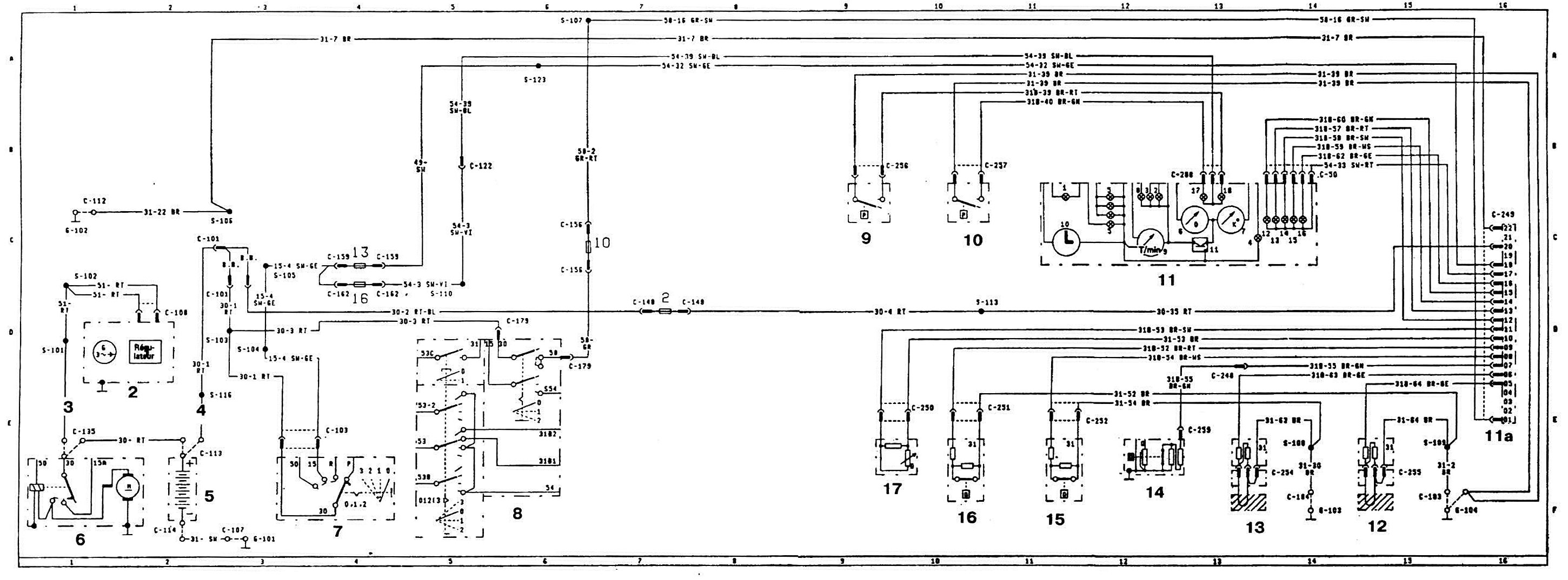
Wiring diagram for control lamps of the Orion car (Escort 3)
Wiring diagram for control lamps of the Orion car.
1 - voltage regulator; 2 - generator; Z and 4 - fusible connection; 5 - 12V battery; 6 — starter; 7 - ignition switch with anti-theft device; 8 — Light/Windshield wiper switch; 9 - economizer switch (yellow); 10 - economizer switch (red); 11 — instrument cluster; 11 a - junction block; 12 — brake lining wear sensor, right side; 13 — left side brake lining wear sensor; 14 — fuel level sensor; 15 — windshield washer fluid level sensor; 16 — coolant level sensor; 17 — oil level sensor.
This article is available at russian, bulgarian, belarusian, ukrainian, serbian, croatian, romanian, polish, slovak, hungarian
Article reviewed: Afanasy Koshelev
See other similar articles for Ford cars:
• Diagram 6a. Speed control system connections Ford Focus 2 (2004-2010)
• Checking the engine compartment wiring Ford Mondeo 1 and 2 (1993-2000)
• Removing the electric throttle control motor Ford Fiesta 2 (1983-1989)
• Automatic transmission control rod lubrication Ford Taurus 1 and 2 (1986-1994)
• Circuit diagram of signaling, turning and control systems Ford Scorpio 1 (1985-1994)
• Control levers Ford Transit 2 (1986-2000, diesel)
• Diagram 6a. Speed control system connections Ford Focus 2 (2004-2010)
• Checking the engine compartment wiring Ford Mondeo 1 and 2 (1993-2000)
• Removing the electric throttle control motor Ford Fiesta 2 (1983-1989)
• Automatic transmission control rod lubrication Ford Taurus 1 and 2 (1986-1994)
• Circuit diagram of signaling, turning and control systems Ford Scorpio 1 (1985-1994)
• Control levers Ford Transit 2 (1986-2000, diesel)
Link to this page in different formats
Visitor comments
No comments yet
Escort 5
Escort 4
Escort 3
- General information
- User manual
- Maintenance
- Engine
- HCS and Endura-E engines
- CVH and PTE engines
- Zetec and Zetec-E engines
- Gasoline engines
- Diesel engines
- Diesel engines (since 1992)
- Cooling and heating
- Carburetors
- CFI fuel injection
- EFI fuel injection
- SEFI fuel injection
- Exhaust system
- Charging and starting system
- Ignition system
- Transmission
- Clutch
- Mechanical gearbox
- Automatic gearbox
- Drive shafts
- Chassis
- Brake system
- Car suspension
- Steering
- Body
- Electrical equipment
- Light and appliances
- Schematic diagrams
Escort 4
- General information
- User manual
- Maintenance
- Gasoline engines
- OHV engine repair
- CVH engine repair
- Fuel system
- Weber 2V carburetor
- KE-Jetronic injection system
- CFI injection system
- Ignition system
- Diesel engines
- Engine repair
- Fuel system
- High pressure pump
- Cooling and lubrication system
- Transmission
- Clutch
- Mechanical gearbox
- Automatic gearbox
- Drive shafts
- Chassis
- Suspension and wheels
- Steering
- Brake system
- Body
- Body elements
- Doors, locks and windows
- Electrical equipment
- Equipment and devices
- Lighting system
- Electrical circuits
Escort 3
- General information
- Maintenance
- Characteristics
- Engine
- Disassembly and assembly
- Cooling system
- Lubrication system
- Supply system
- Fuel injection «K-Jetronic»
- Transmission
- Clutch
- Mechanical gearbox
- Hydromechanical box
- Drive shafts
- Chassis
- Front suspension
- Rear suspension
- Steering
- Brake system
- Electrical equipment
- Starting and charging system
- Ignition system
- Ignition «Escort RS 1600»
- Light and appliances
- Schematic diagrams
