Contents: Lock cylinder ↳ Top latch ↳ Lock and lock opening mechanism ↳ Lock and lock opening device ↳ Interior door lock handle and… ↳
1. In most cases, you will have to remove the door trim to get to the relevant parts (for more details see. in Section 9).
Lock cylinder
Removal
2. Separate the lock lever rod and, where fitted, disconnect the central locking reversing switch from the lock cylinder. Remove the cylinder retaining plate, then remove the cylinder itself.
Installation
3. Installation is carried out in the reverse order of removal.
Top latch
Removal
4. Unscrew the two fixing bolts, separate the connecting rod, and remove the latch (see Figure 14.4).
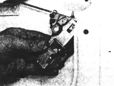
Figure 14.4. Removing the rear door latch.
Installation
5. Installation is carried out in the reverse order of removal.
Lock and lock opening mechanism
Removal
6. Position the upper link so that the clamps can be removed from the links and the links can be disconnected from the lock.
7. Unscrew the three fixing screws and remove the lock. Where fitted, disconnect the central locking multi-pin plug.
8. If necessary, remove the central locking motor (if it is installed) from the lock, for which you should unscrew two screws and turn the engine to separate the thrust.
Installation
9. Installation is carried out in the reverse order of removal.
Lock and lock opening device
Removal
10. Unscrew the fixing screw (see Figure 14.10) and, having partially pulled out the lock opening handle, turn it to disconnect the rod.
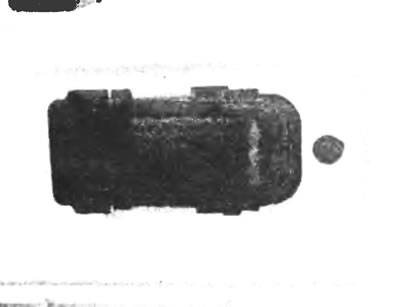
Figure 14.10. Rear door lock opening handle.
11. Disconnect the rods from the outer handle and lock cylinder, and the upper rod from the latch. Unscrew the three locking screws and remove the latch.
12. If necessary, the lock cylinder can be removed by releasing the latch and pulling the cylinder out (see Figure 14.12, a-c).
Installation
13. Installation is carried out in the reverse order of removal. Check the operation of the lock and latch before installing the interior trim.
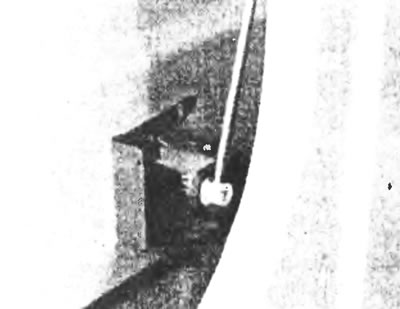
Figure 14.12,a. Rear door lock latch and cylinder.
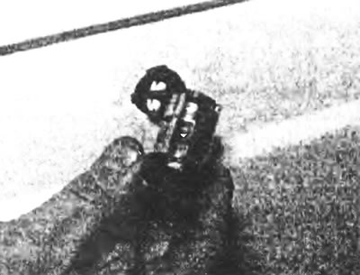
Figure 14.12,b. Removing the rear door lock cylinder.
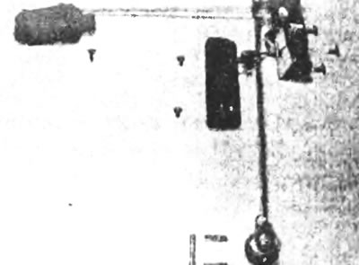
Figure 14.12, c. Interior handle, latch and lock of the rear door - connecting rods and lock mounting screws are shown.
Interior door lock handle and locking plate
Removal
14. To remove the handle, unscrew the Torx screws and disconnect the door clips (upper and lower) (see figure 14.14).
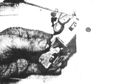
Figure 14.14. Inside handle of the rear door lock.
15. The guide plates of the stoppers in the upper and lower corners of the door can be removed by unscrewing their mounting screws. The door fasteners are removed in a similar manner (see Figure 14.15, a-d).
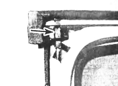
Figure 14.15,a. Upper plate of the rear door (shown by the arrow).
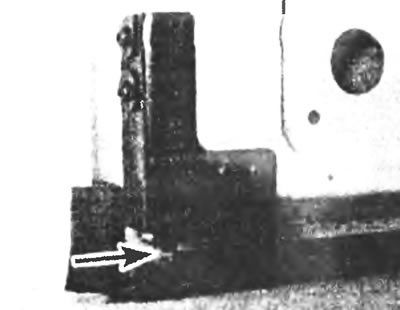
Figure 14.15,b. Rear door lower plate (shown by the arrow).
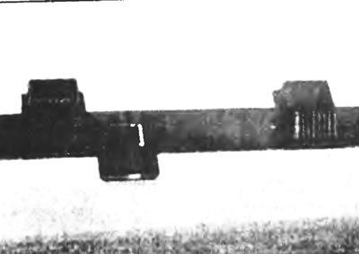
Figure 14.15, c. Guide plate of the lower retainer.
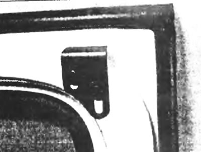
Figure 14.15, d. Upper plate of the rear door.
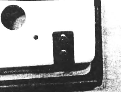
Figure 14.15,d. Lower plate of the rear door.
Installation
16. Installation is carried out in reverse order. If necessary, adjust the position of the retainer plates.