Pen
Removal
1. Remove the inner door trim (see Section 9)
2. Separate the outer handle rod, then unscrew the lock nuts, remove the washers and remove the handle.
Installation
3. Installation is carried out in the reverse order of removal.
Door lock
Removal
4. Remove the inner door trim (see Section 9).
5. Partially open the door, then separate the door latch rod.
6. Unscrew the three fixing screws and remove the lock.
Installation
7. Installation is carried out in reverse order.
Remote control mechanism for the lock
Removal
8. Remove the inner door trim (see Section 9).
9. Remove the covers and unscrew the door latch lever fixing screws.
10. Disconnect the cable, remove the handle and cable.
11. Disconnect the lock rod. Loosen the latch and outer handle rod screws, release the lock and remove the short handle rod (see figure 12.11.).
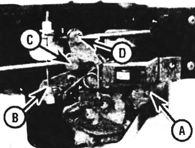
Figure 12.11. Remote control mechanism of the lock: A - Lock rod and latch, B - Handle cable, C - Lock rod, D - Handle rod
12. Carefully drill out the locking rivets of the remote control mechanism and remove the mechanism.
Installation
13. Installation is carried out in the reverse order of removal. When installing the assembly in place, check that the latch rod is aligned with the lower locking lug and engaged with the outer handle rod. Align the assembly with the rivet holes and secure with new rivets.
14. Adjust the latch and remote control rods of the lock, then install the inside handle cable, lock rod and trim.
Guides
Top guide
15. Open the door, then unscrew the fixing screws and separate the upper door support. Drill out the rivets and remove the top guide. The guide is installed in the reverse order of removal. Adjust the position of the top guide and tighten the screws.
Central
16. Remove the side door as described in Section 13.
17. After unscrewing the fixing screw on the rear end of the door opening and the fixing nuts inside the cabin, remove the guide (see figure 12.17,a,b). Note that the rear nut also secures the guide end stop.
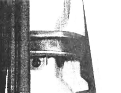
Figure 12.17,a. Unscrew the fixing screw on the guide...
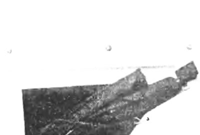
Figure 12.17, b....and the nuts of the fixing studs from the inside.
18. Installation is carried out in the reverse order of removal.
Bottom guide
19. Open the side door, remove the round cover from the footrest and unscrew the two fixing screws (see figure 12.19,a,b).
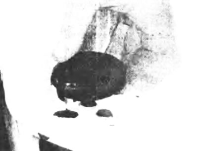
Figure 12.19,a. Remove the round cover from the footrest...
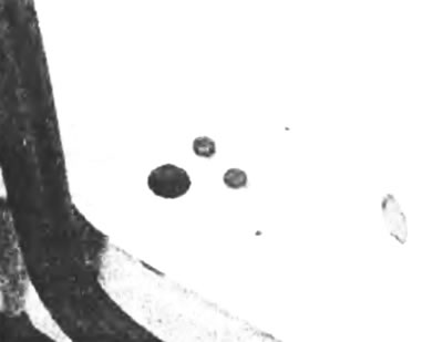
Figure 12.19, b....and unscrew the two fixing screws of the lower guide.
20. Unscrew the two screws and separate the lower guide bracket (see Figure 12.20).
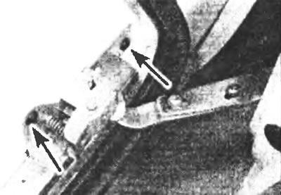
Figure 12.20. Unscrew the two screws (indicated by arrows) and disconnect the lower guide bracket from the body.
21. Unscrew the fixing screws and remove the lower guide together with the lower latch
22. Install in the reverse order of removal. Check that the door moves smoothly and closes securely.