Contents: Resistance check ↳ Replacement ↳
Resistance check
1. After installing the antenna wire on the vehicle and disconnecting the radio cable, check the antenna at the indicated points using an ohmmeter (see figure). If the readings are not within the acceptable range, replace the antenna and cable assembly.
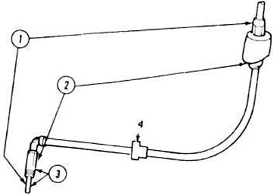
15.1, a. Checking the resistance between the antenna mast and the cable.
1. Should be below 5.0 Ohm per x1mm.
2. Should be below 5.0 Ohm per x1mm.
4. Spacer ring.
3. Should be at infinity (00)x1000 setting. Higher level is acceptable.
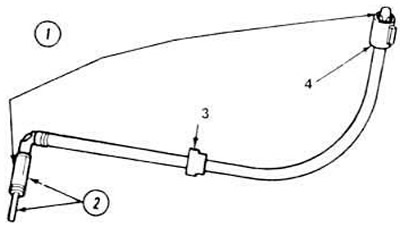
15.1, b. Checking the resistance between the antenna cable and the base.
1. Should be below 5.0 Ohm per x1mm.
2. Should be at infinity (00)x1000 settings, a higher level is acceptable.
3. Spacer ring.
4. Conductor.
Replacement
1. Disconnect the negative battery cable.
2. Push the side walls of the glove compartment door inward, lower the entire door down.
3. Disconnect the antenna wire from the back of the radio.
4. Remove the cable from the clips and retainers under the instrument panel (see figure).
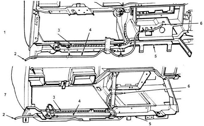
15.4. Antenna cable routing.
1. Taurus.
2. To the antenna.
3. Wire block.
4. Cable block.
5. Instrument panel.
6. To the radio.
7. Sable.
5. Remove the right front fender liner by pulling out the center parts of the plastic clips with pliers. Unscrew the screws, disconnect the liner, lower it down.
6. Disconnect the antenna cable. On antennas with electric lift, disconnect the power supply.
7. Pass the antenna cable through the hole in the door hinge cushion and remove it through the wing wall.
8. For mechanical antennas, unscrew the antenna mast with a wrench and remove it from the vehicle.
9. Using a wrench or socket head, unscrew the nut.
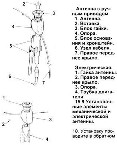
10. Perform installation in reverse order.