Contents: Rear Window Defogger Switch ↳ Rear Window Defogger Grille Wire ↳ Servicing the power supply wire… ↳
Rear Window Defogger Switch
1. The rear window defroster switch is located on the left trim panel or instrument cluster panel. To check, detach the trim panel from the instrument panel, turn it over and locate the heater switch electrical connector
2. According to the instructions (see figure), ground pin G and connect the connecting wire between pins I and B. And install a 12-volt test lamp between the ground and pin L.
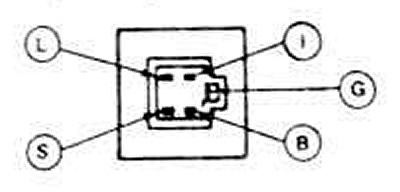
18.2. Location of contacts when checking the rear window defroster switch.
3. Apply power to pin B. The control lamp should not light.
4. Very quickly turn the switch to the "on" position. The light should come on and remain on after the control link returns to its normal position.
5 The light should go out under the following conditions:
- a) if the switch is moved to the "on" position"
- b) if voltage is not supplied to the additional (ACC) ignition contact or approximately 10 minutes have passed
6. Apply power to pin S. The indicator light should come on.
7. If the switch fails any of these tests, replace it.
8. To replace, pull out the electrical connector and remove the switch from the air conditioner heater control unit.
9. Install in reverse order.
Rear Window Defogger Grille Wire
Examination
10. Start the engine and let it idle. Set the control switch to the on position. The indicator light should come on.
11. Working inside the car with a voltmeter, connect the wide red-brown strips on the sides of the rear window. The measurement should read 10-12 volts. A lower voltmeter reading indicates a poor ground wire connection on the grounded side of the glass.
12. Find a good ground for the negative lead of the measuring device. The measured voltage value should not change.
13. Ground the negative wire of the measuring device with the positive contact and touch each grille bar in the middle of its height with the rear window heated:
- a) a value of approximately 6 volts indicates that everything is OK.
- b) a value of 0 volts indicates a break in the line between the midpoint and the positive side of the grid circuit.
- c) a reading of 12 volts indicates a break in the circuit between the midpoint and ground.
Repair
Note: Breaks in grid lines longer than 25mm (1") cannot be repaired. For shorter breaks, use grid repair compound and brown touch-up.
14. Work should be carried out at room temperature (16 degrees Celsius (60 degrees Fahrenheit) and above).
15. Clean the entire mesh area to be repaired with glass cleaning solvent. Remove all foreign matter - dirt, wax, grease, oil, etc. The area to be repaired must be dry and clean.
16. Mark the location of the gap on the outside of the window.
17. Cover the area above and below the tear with tape. The tear should be in the center of the covered area, the distance between the upper and lower tape should not be wider than the thickness of the grid line (see figure).
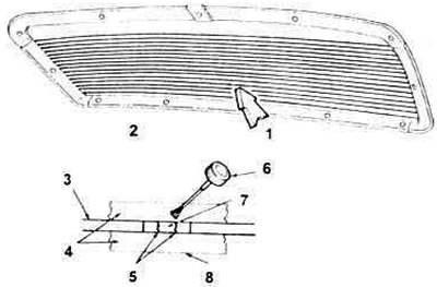
18.18. Parts for repairing the rear window defroster mesh.
1. Type A.
2. Using tape, cover the area above and below the break in the mesh. The repaired area should be in the center of the covering, and the gap between the upper and lower tape should not be wider than the mesh line.
3. Grid.
4. Tape.
5. Place of rupture.
6. Brush for applying the composition.
7. Apply brown touch-up to this area first - if the brown mesh layer is damaged or missing.
8. Cover the gap on both sides with tape at least 6.35 mm (1/4 inch) wide.
18. If the brown and silver grid lines are broken or missing, first apply a coat of brown touch-up paint across the broken area. It may take two coats to achieve the desired color. Let the touch-up paint dry.
19. Apply three coats of silver grill repair compound, allowing three to five minutes to dry between coats. The silver compound should overlap the tear by at least 14 inches on each side
Note: If the brown layer of the mesh is not torn or missing, apply only the silver compound to the tear. Let the compound dry for 5 minutes, then remove the frame.
20. Check the results of the mesh repair from the outside. If the silver layer is visible above or below the mesh, the excess should be removed. This can be done with a razor blade.
Be careful not to damage the grid line with the razor blade.
21. The applied coating should air dry for a minute, then be turned on for three to five minutes. Normal setting and hardening occurs after about 24 hours. After this, the repaired area can be cleaned with a mild glass cleaner.
Servicing the power supply wire contact
22. Let the rear window of the car warm up to room temperature for half an hour to an hour.
23. Clean the busbar in the repair area.
24. Apply three coats of grid repair compound to restore the original busbar contact connection area. Allow approximately 10 minutes drying time between coats.
25. Tin the busbar with solder in the area where the contact was removed, and work as quickly as possible so as not to heat the glass.
26. Before soldering the contact, preheat the glass in the solder area with a heating lamp to a temperature of 50-65 degrees Celsius (120-150 degrees Fahrenheit).
27. Place the contact on the busbar and hold it in place with a screwdriver (see figure).
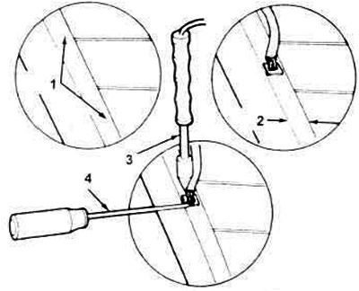
18.28 Place the contact on the busbar in the tinned area and hold it in place with a holder or screwdriver.
1. Busbar.
2. Repair area.
3. Soldering iron.
4. Holder.
28. Place the soldering iron on the base of the contact and hold until the solder melts.
Note: To avoid damaging the busbar and overheating the glass, remove the soldering iron as soon as the solder melts.
29. Start the engine, turn on the heated rear window and leave for five minutes.
[A copy of the article is available on the website: fordbook]