The basic principle of ignition is that the battery current flows through the primary winding of the ignition coil, which is made of several turns (about 100) of thick copper wire. The effect of the electric current creates a strong magnetic field around the iron core in the ignition coil, i.e. the energy of the current is converted into the energy of the magnetic field.
As the piston approaches TDC in the compression stroke, when the fuel mixture should be ignited, the electrical current to the ignition coil is interrupted.
When the electric current is interrupted, the magnetic field disappears, inducing a high-voltage current in the secondary winding of the ignition coil, which is made from a large number of turns of thin wire (cross-section of about 0.1 mm²).
TECHNICAL DICTIONARY
Sensors
Pressure sensor.
Connected by a hose to the suction pipe, it transmits information about the vacuum in the suction pipe to the control unit. The sensor is made in the form of a pressure-sensitive crystal chip. It reacts to the vacuum at the moment by changing its electrical resistance. From these indicators, as well as information about the crankshaft rotation frequency at the moment, the control unit determines the current operating state of the engine.
Knock sensor.
The combustion process of fuel in the engine cylinders is controlled by the engine control unit based on information received from the knock sensor. Detonation combustion of fuel occurs when the ignition is too early and the engine is running on fuel with a low octane number. Detonation occurs when the flame propagation speed in the combustion chamber approaches the speed of sound, mainly towards the end of the combustion process, and the residual gases are sufficiently compressed and have a high temperature. Detonation is characterized by very high pulse pressure, which leads to engine overheating, damage to the piston, cylinder head and crankshaft bearing liners.
The knock sensor reacts to the high-frequency vibrations of the cylinder block that occur during detonation and transforms them into electrical signals that are sent to the control unit. This information is then compared with the signals received during combustion of fuel without detonation. When detonation occurs, the ignition timing is delayed until the combustion process is normal.
Crankshaft speed sensor.
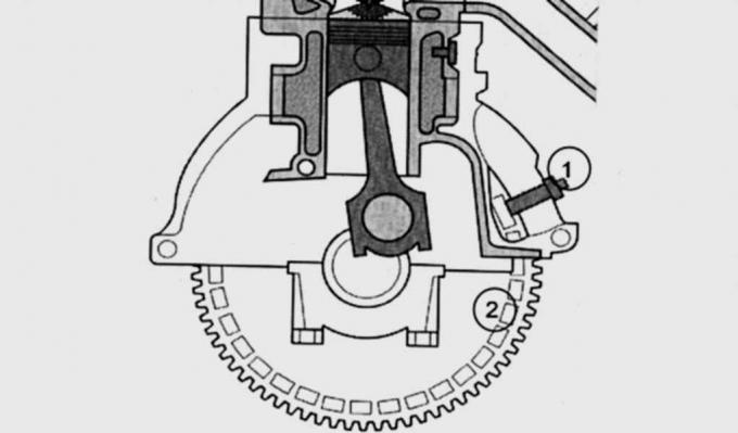
Fig. 9.2. Location of the inductive pulse sensor that transmits information about the rotation speed and position of the crankshaft to the control unit: 1 – inductive sensor; 2 – rotor plates
The inductive sensor has a coil made of wire winding and a magnet. The mating part is a rotor consisting of plates of a certain size (Fig. 9.2). Each time a rotor plate passes near the pulse sensor, the magnetic field changes, causing a pulse voltage to be induced in the coil winding. Based on the number of pulses, the control unit calculates the engine crankshaft speed.
To calculate the ignition timing, the control unit requires information about the crankshaft position. For this purpose, the rotor for cylinders 1 and 4 has two longer plates before the top dead center of each cylinder. When passing the section of the rotor with the longer plates, it does not induce voltage for a short moment. Based on the short absence of voltage pulses, the control unit determines the position of the engine crankshaft for cylinders 1 and 4.
This high-voltage current from the ignition system is fed directly to the spark plug, between whose electrodes a spark discharge is formed. The fuel mixture ignites and presses on the piston, which, via the connecting rod, turns the engine crankshaft. The electrical circuit is turned on again, and the cycle is repeated.
Models from the 96th series are equipped with an electronic ignition system with two ignition coils. With each control pulse of current supplied by the control unit, the ignition coil sends a pulse to two spark plugs at once. One spark discharge ignites the fuel mixture at the end of the compression stroke, and the second occurs on the exhaust stroke, where the ignition spark has no effect on the operation of the engine and is therefore wasted. After further rotation of the crankshaft, the ignition coil again sends an ignition pulse to two spark plugs at once, but this time, where previously the spark discharge occurred in the cylinder on the exhaust stroke, the end of the compression stroke occurs and the fuel mixture ignites, and vice versa. The ignition pulses ensure the following sequence of cylinder operation 1-3-4-2 (Endura-E: 1-2-4-3).
Source of spark.
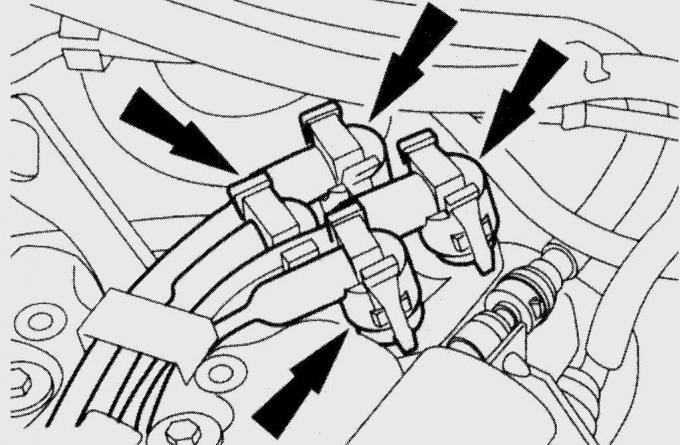
Fig. 9.3. Location of fastening clamps for high-voltage wire connectors
The electronic ignition unit has little in common with a conventional ignition coil. Sensors, transistors and diodes distribute the ignition sparks to individual cylinders in the control unit. In Zetec-SE engines, the ignition coil is located under the engine trim. To disconnect the high-voltage ignition wire, it is necessary to squeeze the tabs of the clamps on the electrical connectors (Fig. 9.3).
(The text was obtained in its entirety from the specified website: FORDBOOK.RU)