

SEQUENCE OF WORKS
1. Loosen the wheel hub nut and wheel bolts while pressing the brake pedal.
2. Raise the car horizontally and secure it on supports. Remove the front wheel.
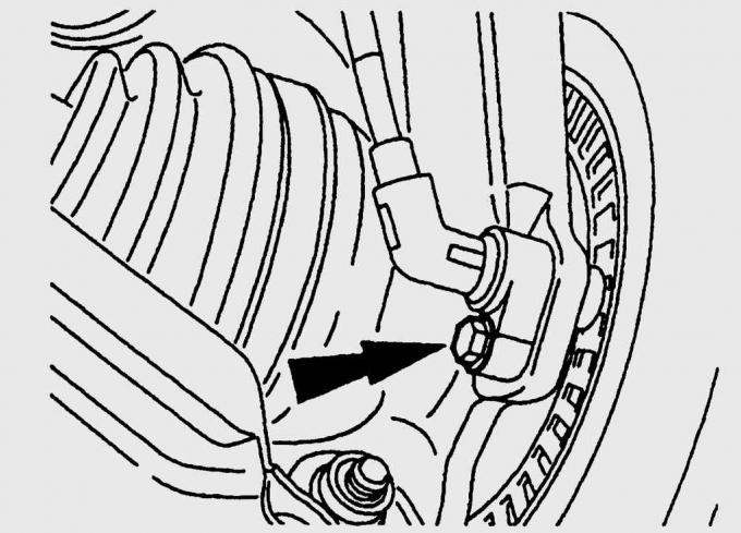
Fig. 13.14. Location of the ABS sensor on the steering knuckle
3. Loosen the bolt and remove the ABS sensor from the steering knuckle (Fig. 13.14).
4. Loosen the bolts, remove the caliper and secure it in the wheel arch with soft wire so that the brake hose does not stretch or twist.
5. Loosen the brake disc mounting bolts and remove the disc from the wheel hub. Knock off a tightly seated disc with light blows of a plastic hammer or remove it with a puller.
6. Remove the tie rod end.
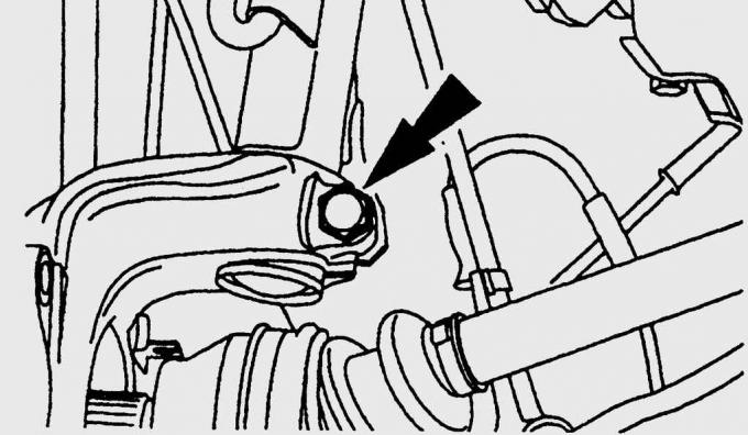
Fig. 13.15. Location of the lower shock absorber strut mounting bolt to the steering knuckle
7. Unscrew the bolt securing the lower part of the shock absorber strut to the steering knuckle (Fig. 13.15).
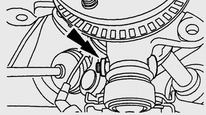
Fig. 13.16. Location of the nut and bolt securing the ball joint of the lower arm to the steering knuckle
8. Loosen the nut, remove the bolt and push the lower arm ball joint out of the steering knuckle (Fig. 13.16). Be careful not to damage the ball joint protective boot.
9. Disconnect the lower part of the shock absorber strut from the steering knuckle.
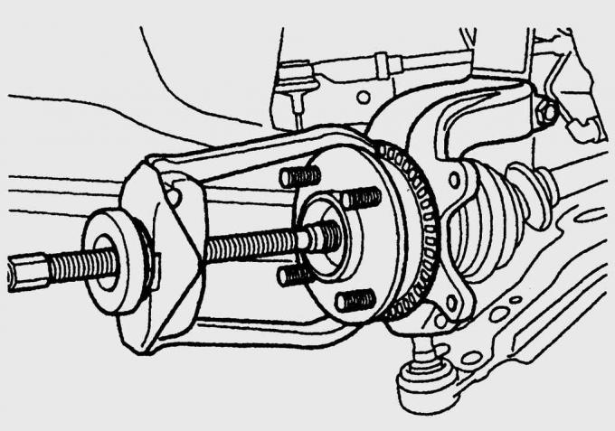
Fig. 13.17. Using a puller to remove the steering knuckle from the drive shaft
10. Completely unscrew the free wheel hub mounting nut and use a puller to remove the steering knuckle from the wheel drive shaft (Fig. 13.17). The drive shaft should not come out of the inner constant velocity joint.
11. To prevent damage to the inner constant velocity joint when the drive shaft is sagging, secure the shaft with soft wire.
12. Remove the steering knuckle together with the wheel hub bearing.
(The text is available on the specified website info portal: «FORDBOOK.ru»)