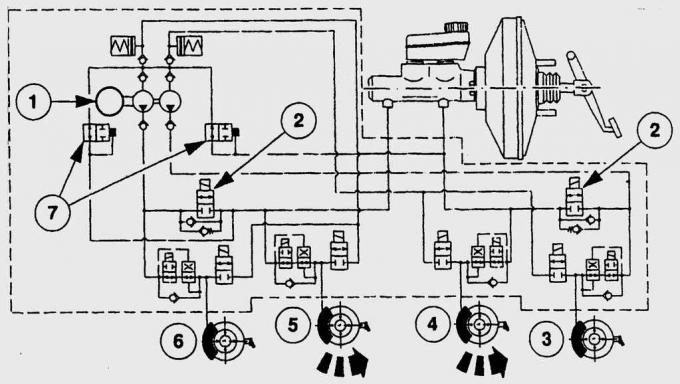
Pic. 14.2. Scheme of interaction of elements of the brake system: 1 - pump; 2 – BTCS valve; 3 - front wheel; 4 - rear wheel; 5 - rear wheel; 6 - front wheel; 7 - hydraulic inlet valves
The main brake cylinder together with the vacuum brake booster is located in the engine compartment. Since 1996, the diameter of the vacuum brake booster has been increased to 229 mm (instead of 203 mm), the gain increased from 4 to 4.5. The diameter of the main brake cylinder has also been increased. The pistons compress the brake fluid contained in the main brake cylinder, the hydraulic pressure created in the brake system is transmitted through pipelines and hoses to the calipers of all four wheels (pic. 14.2). In the front calipers, pistons press the brake pads against the brake discs. In the rear wheels, the pistons of the wheel brake cylinders press the brake pads against the brake drums.
The parking brake acts through the cables on the brake mechanisms of the rear wheels, compared to older models, it is more effective and requires less effort. In modern Fiesta models, the parking brake is adjusted inside the car, which, among other things, significantly reduces maintenance costs.
The Fiesta has self-adjusting disc and drum brakes, with an expensive adjustment mechanism on the rear axle.
The most important elements of the brake system
Brake system with two brake circuits.
The car is equipped with a working brake system with a diagonal separation of circuits, i.e. each circuit provides braking to the front and diagonally located rear wheel. If one of the circuits fails, the second circuit is used to stop the car with sufficient efficiency.
Master brake cylinder.
Converts brake force into hydraulic pressure. When the brake pedal is released, the pressure in the brake system is quickly reduced.
Vacuum brake booster.
The vacuum brake booster reduces the force required to apply when pressing the brake pedal by up to 60%, thereby facilitating driving. The principle of operation of the vacuum brake booster is based on the use of vacuum in the intake manifold or created by a vacuum pump (on vehicles with diesel engines). When braking, the diaphragm connected to the master cylinder rod reacts to the difference between the pressure of atmospheric air and the pressure in the intake manifold.
Wheel brake cylinder.
The brake fluid pressure in the wheel brake cylinder can be up to 120 bar. The wheel hydraulic cylinder pistons transmit force to the disc or drum brake pads.
TECHNICAL DICTIONARY
Brakes
Front brakes
Brake disk.
Rotates synchronously with the axle hub and removes heat generated by friction during braking.
Caliper.
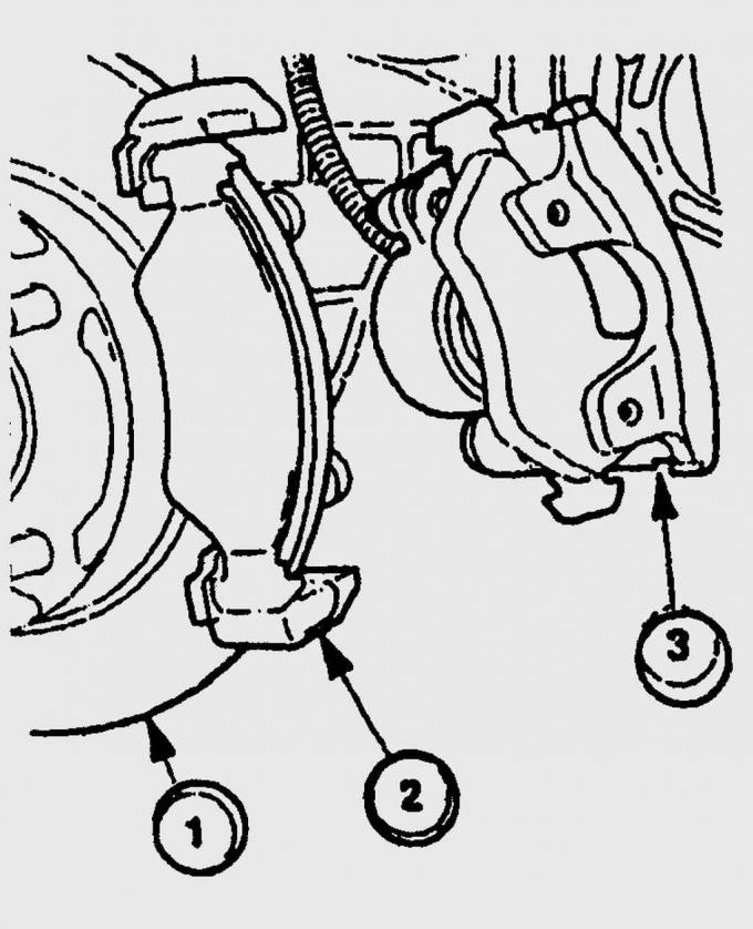
Pic. 14.3. The brake mechanism of a forward wheel: 1 – a brake disk; 2 - guide brake shoes; 3 - support
A steel brake disc rotates freely with the wheel, and the brake caliper covers the disc on both sides (pic. 14.3). When you press the brake pedal, the caliper piston presses the brake pads against the brake disc - due to friction between them, the car is braked.
During braking, kinetic energy is converted into heat energy due to friction, which is removed from the friction zone by the brake disc and caliper. Since heat transfer occurs through one caliper cylinder, the brake fluid does not heat up very much.
Pressing the brake pedal.
When you press the brake pedal, a rod connected to the pedal presses on two pistons located one behind the other in the master brake cylinder. The pistons compress the brake fluid contained in the master cylinder, the hydraulic pressure thus created is transmitted through pipelines and hoses to the calipers of all four wheels. In the calipers, the pistons press the brake pads against the brake discs, causing the vehicle to brake.
Releasing the brake pedal.
The pressure in the hydraulic system instantly decreases, and the caliper piston, along with the brake pads, moves away from the brake disc. A gap is formed between the brake pads and the disc, the brake disc begins to rotate freely and the braking process stops.
Rear brakes
Drum brakes.
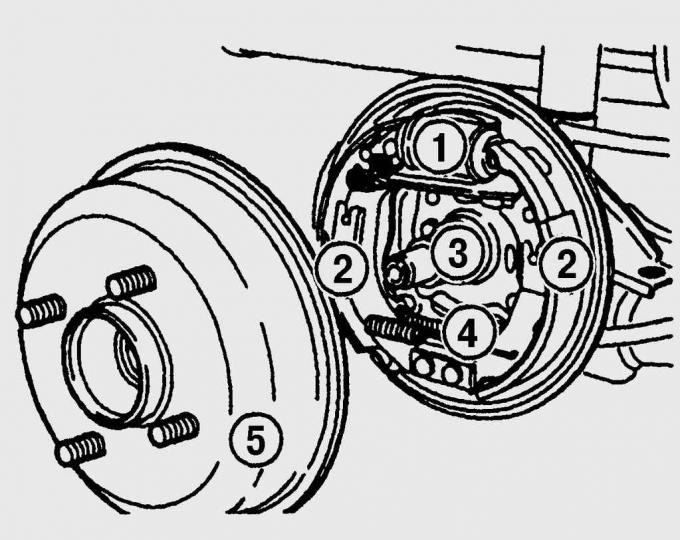
Pic. 14.4. The brake mechanism of a back wheel: 1 – the wheel brake cylinder; 2 - brake shoe; 3 - the axis of the hub; 4 - parking brake cable; 5 - brake drum
The Fiesta has single-acting brakes on the rear axle, consisting of two semi-circular brake pads (pic. 14.4). Front brake lining thickness (incoming brake pad) more than the thickness of the back (push-in brake pad). A two-piston wheel brake cylinder presses both pads against the brake drums. At the same time, they are mounted on a support pin located on the opposite side from the wheel brake cylinder. The pin is riveted to the rear brake guard.
TECHNICAL DICTIONARY
Anti-Lock Braking System
ABS control unit.
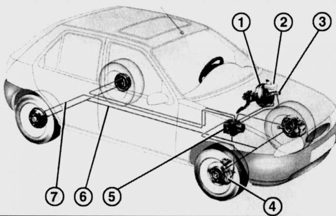
Pic. 14.5. The location of the elements of the anti-lock braking system on the car: 1 - vacuum brake booster; 2 - reservoir with brake fluid; 3 - the main brake cylinder; 4 - front brake caliper; 5 – electrohydraulic block; 6 - electrical circuit connecting the wheel speed sensors with the electro-hydraulic unit; 7 – pipelines of a hydraulic drive of brakes
Constantly processes information about the speed of the vehicle's wheels received from the sensors and compares it with the programmed values (pic. 14.5). With a difference in speed values, indicating an imminent danger of blocking one or more wheels, the control unit activates the hydraulic unit - the pressure of the brake fluid on the blocking wheel decreases until it begins to rotate again synchronously with other wheels. This cycle of pressure change occurs in a matter of milliseconds. In addition to signal processing and subsequent valve control, the control unit also performs a diagnostic function. It checks and registers malfunctions in electrical circuits or elements of the anti-lock braking system, the operating voltage in the vehicle's on-board network, warning the driver by lighting up a warning lamp in the instrument cluster.
Electrohydraulic block.
It consists of an electric pump and a valve block with solenoid valves. When the brake pedal is depressed, the pistons in the master cylinder force the brake fluid through the valve block to the wheel brakes. In this case, the valve block regulates the pressure in the brake circuits, which diagonally connect the front wheel to the rear wheel. If the ABS system is activated, the control unit issues a signal to reduce the pressure and brake fluid is supplied directly from the valve block to the brake fluid reservoir. If the brake pressure needs to be increased again, the brake fluid is pumped from the reservoir via a hydraulic pump directly into the appropriate brake hydraulic circuit. The operation of the pump can be seen by a slight pulsation of the brake pedal. The cycle of braking and free spinning of the wheel is very fast and continues until the vehicle comes to a stop or until the brake pedal is released.
Wheel speed sensor.
Speed sensors, one for each wheel, measure the wheel speed, and based on their signals, the electronic control unit calculates an average speed that approximately corresponds to the speed of the vehicle. By comparing the rotational speed of each individual wheel with the average calculated speed, the electronic unit determines the slip state of the individual wheel and thereby determines which wheel is in the pre-lock state.
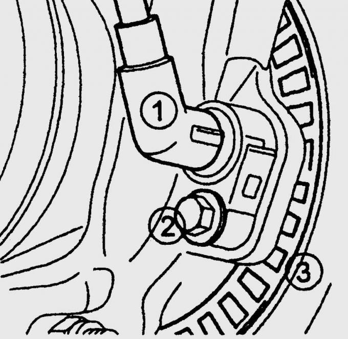
Pic. 14.6. Location of the front wheel ABS sensor: 1 – ABS sensor; 2 – a bolt of fastening of the gauge; 3 - toothed rotor
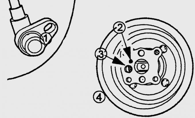
Pic. 14.7. Location of rear wheel ABS sensor: 1 – ABS sensor; 2 – a bolt of fastening of the gauge; 3 – hole for installing the sensor; 4 - brake drum
The speed sensor, consisting of a magnetic armature and a coil, is installed with a small gap from the gear rotor rotating with the wheel (pic. 14.6, 14.7). Each tooth of the rotor, passing by the sensor, induces a short voltage pulse in it. Thus, the sensor generates an alternating voltage, the frequency of which increases or decreases in accordance with the speed of the wheel, and transmits it to the control unit.
Longitudinal acceleration sensor.
It consists of two reciprocating switches that are installed under the center console in the car. During normal driving and slight acceleration or braking, they are inoperative. As soon as the braking or acceleration parameters programmed in the control unit are exceeded, the sensors send a corresponding signal to the control unit.
Faults in the brake system with ABS.
The ABS warning lamp in the instrument cluster comes on after the ignition is switched on and goes out 2 seconds after the engine is started. If the control lamp burns constantly, ABS is faulty. If the ABS system is faulty, the brakes are still serviceable and function as if they were not equipped with ABS. To fix the problem, you must contact the auto repair shop. In any case, it is necessary to check the reliability of connecting the connectors to the control unit and wheel speed sensors.
Visitor comments