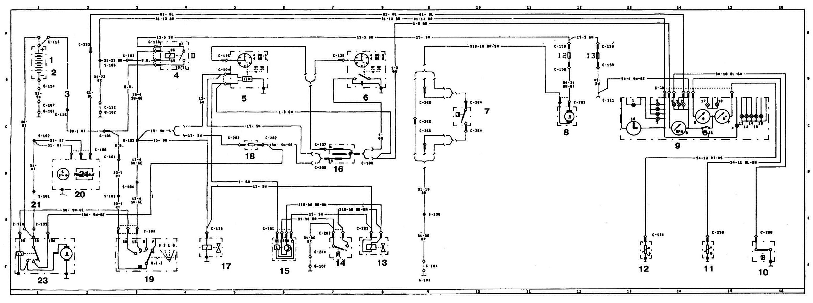
Wiring diagram of charging, starting and control systems for Ford Escort vehicles manufactured in 1980-1982.
1 - 12 V; 2 — A/B; 3 - fusible link; 4 — ignition relay; 5-sensor-distributor; 6 — ignition distributor; 7 — Cooling system fan motor switch; 8 — electric motor of the cooling system fan; 9 — instrument cluster; 10 — oil pressure sensor; 11 — fuel level sensor; 12 - coolant temperature sensor; 13 — exhaust gas recirculation valve; 14 - vacuum sensor; 15 — exhaust gas recirculation system control unit; 16 - ignition coil; 17 - electromagnetic shut-off valve; 18 - additional ignition coil resistor; 19 - ignition switch with anti-theft device; 20 — generator; 21 - voltage regulator; 22 - fusible link; 23 — starter.