Contents: The new Zetec-SE four-cylinder… ↳ Technical cooperation with Yamaha… ↳ Cylinder block and cylinder head ↳ The 1.25i Zetec-SE engine with a… ↳ Combination of Zetec-SE engine and… ↳ Zetec-SE 1.4i engine (66 kW/ 90 hp) ↳ Endura-E engines (37 kW/ 50 hp, 44… ↳ Suction pipe made of plastic ↳ Sequential fuel injection is… ↳ 1.8 l OHC diesel engine (44 kW/60… ↳ Technical solutions for reducing… ↳ Choosing the best option for engine… ↳ Engine models for Fiesta car ↳ Cranking the engine crankshaft ↳
Under the hood of the Fiesta cars are installed compact transversely mounted four-cylinder engines with two or four (Zetec-SE) valves per cylinder. Since 1996, all petrol engines are equipped with electronic control (Ford EEC-V) with a contactless 3D ignition system and electronic fuel injection (SEFI). The modern 1.8D Endura-DE engine is equipped with a diesel fuel injection system directly into the swirl chambers. The range of engines of the modified Ford Fiesta car is at a high technical level. All petrol engines are equipped with a controlled three-way catalytic converter, and the diesel engine is equipped with an oxidation catalytic converter, and an exhaust gas recirculation system. All engines comply with the prescribed exhaust gas toxicity standards according to 96 EEC.
The new Zetec-SE four-cylinder engine, fitted to Fiesta cars since 1996
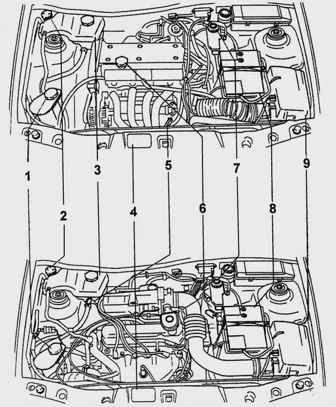
Fig. 4.1. Engine compartments with Zetec-SE 1.25 and 1.4 l engines (top) and Endura-E 1.3 l (bottom): 1 – power steering reservoir; 2 – washer reservoir; 3 – expansion tank of the cooling system; 4 – vehicle data plate; 5 – Engine oil level indicator; 6 – oil filler neck; 7 – brake fluid reservoir; 8 – battery; 9 – air filter
It is undeniable that the Zetec-SE DOHC engines with a displacement of 1.25 l (55 kW / 75 hp) and, respectively, 1.4 l (66 kW / 90 hp) have been the technical perfection of the Fiesta series cars since 1996. In the engine compartment, the engines are installed with an inclination of 12° to the rear. Incidentally, these are the first transversely installed Ford engines in which the injection system elements are located on the front side of the cylinder head. This solution significantly improves access to all injection system elements during repair and maintenance. The inclination angle is of great importance, since with the "turning" of the cylinder head, the exhaust system is no longer in the cooling air flow, but "hides" behind the engine. This inclination provides a lot of space between the engine and the front bulkhead to reduce the transfer of heat to the engine from the exhaust manifold and catalytic converter. The engine compartments of the Zetec-SE 1.25 and 1.4 l and Endura-E 1.3 l engines are shown in Fig. 4.1.
Technical cooperation with Yamaha Corporation
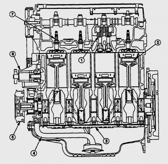
Fig. 4.2. Sectional view of the Zetec-SE engine: 1 – valve mechanism; 2 – piston; 3 – oil deflector plate; 4 – oil intake tube; 5 – vibration damper; 6 – water pump; 7 – spark plug
Both Zetec-SE engines, with displacements from 1.1 to 1.7 litres, are the forerunners of a whole series of engines that were developed by Ford in cooperation with Yamaha. The compact four-cylinder engines feature four valves per cylinder and electronic control, as well as the use of a new generation of Ford's engine control unit (EEC-V). This has made it possible to implement precise control of the air-fuel mixture supply and ignition, as well as improve diagnostics and idle speed regulation. In practice, these solutions have led to a reduction in harmful emissions with exhaust gases and a more uniform combustion process at all loads. A further innovation of the Zetec engines is the very high degree of filling of the cylinders and, as a result, a high specific power of 44.3 kW / l. This becomes even more significant when considering the effective mean pressure, which is an indicator for the efficiency in the form of a specific torque. The mean pressure of all Zetec-SE engines is significantly higher than that of other Ford engines in this class. The sectional and front views of the Zetec-SE engine are shown in Fig. 4.2 and 4.3.
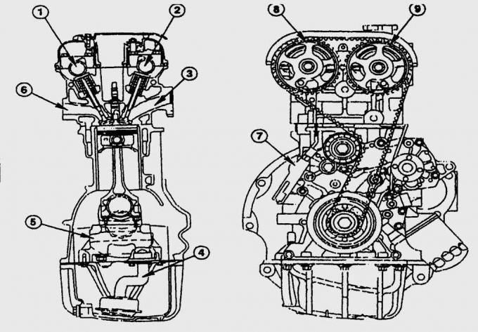
Fig. 4.3. Front view of the Zetec-SE engine: 1 – exhaust camshaft; 2 – intake camshaft; 3 – inlet channel; 4 – oil intake tube; 5 – crankshaft; 6 – outlet channel; 7 – hydraulic tensioner for toothed belt; 8 – exhaust camshaft pulley; 9 – intake camshaft pulley
Cylinder block and cylinder head
The cylinder block and cylinder head, as well as the housings of most additional units and assemblies, are made of a special aluminum alloy. The valve cover is made of magnesium, and the intake pipe is made of plastic. The engines have two overhead camshafts (DOHC) and are equipped with a multi-valve mechanism - four valves per cylinder. A number of design solutions made the engine quieter, reduced its vibration and emissions of harmful substances with exhaust gases, and minimized the time for maintenance. Thanks to hydraulic compensation of valve clearances, the valve clearances are checked in a car repair shop only every 150,000 km of the car's mileage. The valve clearance on a cold engine is 0.17-0.23 mm for intake valves and 0.27-0.33 mm for exhaust valves. Spark plugs are replaced after every 45,000 km, engine oil and oil filter - after 15,000 km of the car's mileage.
The 1.25i Zetec-SE engine with a displacement of 1.25 litres (55 kW/75 hp) has the same power as a conventional 1.4 litre engine
The new 16-valve 1.25-litre engine delivers the same power as a conventional 1.4-litre engine. However, its concept places the least emphasis on absolute figures such as dynamics and fuel consumption. With its exceptionally smooth torque curve, the engine does not constantly require the highest crankshaft speed, but feels at home already at 2,000 min⁻¹ (Fig. 4.4). The 1.25i engine already reaches its maximum torque of 110 Nm at 4,000 min⁻¹. It develops its maximum power of 55 kW / 75 hp at 5,200 min⁻¹. This is enough to feel at ease in normal traffic (acceleration from 0 to 100 km/h in 12.7 s) and to accelerate the Fiesta to 170 km/h on the motorway. Fuel consumption is modest – the 1.25i engine consumes only 6.4 liters of gasoline per 100 km.
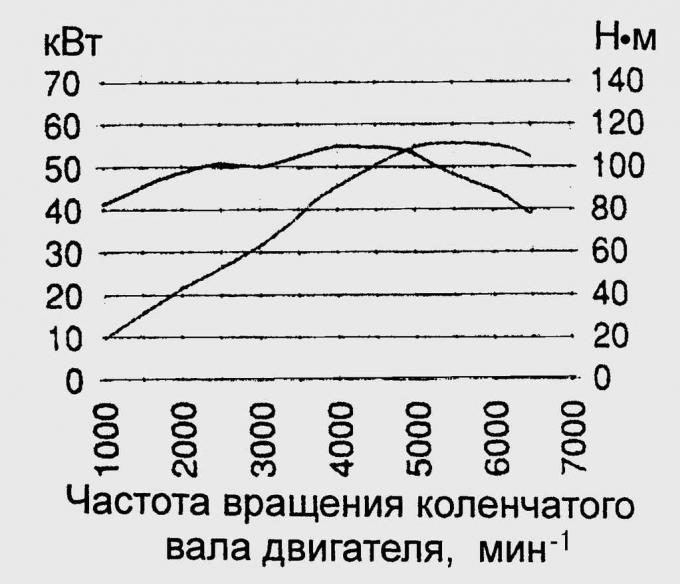
Rice. 4.4. Zetec 1.25 l, 55 kW (75 hp) engine power diagram
Combination of Zetec-SE engine and CTX automatic transmission
Ford combines the Zetec engine with the continuously variable automatic transmission CTX. And although in this combination the dynamism of the 1.25i engine is lost with the automatic transmission, the Fiesta still has high dynamic characteristics. It accelerates from zero to 100 km/h in 15.6 seconds, and the maximum speed of the Fiesta CTX reaches 160 km/h. All this happens at a high level of comfort without switching and with relatively low fuel consumption - 6.7 liters of gasoline per 100 km.
Zetec-SE 1.4i engine (66 kW/ 90 hp)
With a fuel consumption of 6.9 l/100 km, the Zetec-SE 1.4i engine can compete with most conventional 1.6-litre engines. It is also at the forefront in terms of power figures: 66 kW/90 hp at 5,600 rpm – a high figure for any spirited Fiesta driver. The 1.4i accelerates the car from 0 to 100 km/h in 10.8 s, and the top speed is 180 km/h. The Fiesta"s most powerful Zetec-SE engine with a 1.4-litre capacity already provides sufficient traction at 2,000 rpm. The 1.4i engine reaches its maximum torque of 125 Nm at 4,500 rpm.
Endura-E engines (37 kW/ 50 hp, 44 kW/ 60 hp) have been standard equipment in vehicles since 1996
As an alternative to the two Zetec-SE engines, Ford offers the Fiesta with two other petrol engines. The engines have a capacity of 1.3 litres and are internally designated Endura-E. The basic version has an output of 37 kW/50 hp at 4,500 min⁻¹ (Fig. 4.5). The more powerful engine of the Endura-E duo has an output of 44 kW/60 hp at 5,000 min⁻¹. The Endura-E engines are thoroughly modified versions of the OHV-HCS injection engine that has been working flawlessly in the Fiesta for many years. But compared to the proven "original", Ford has significantly improved the Endura-E engines in terms of smoothness and exhaust emissions.
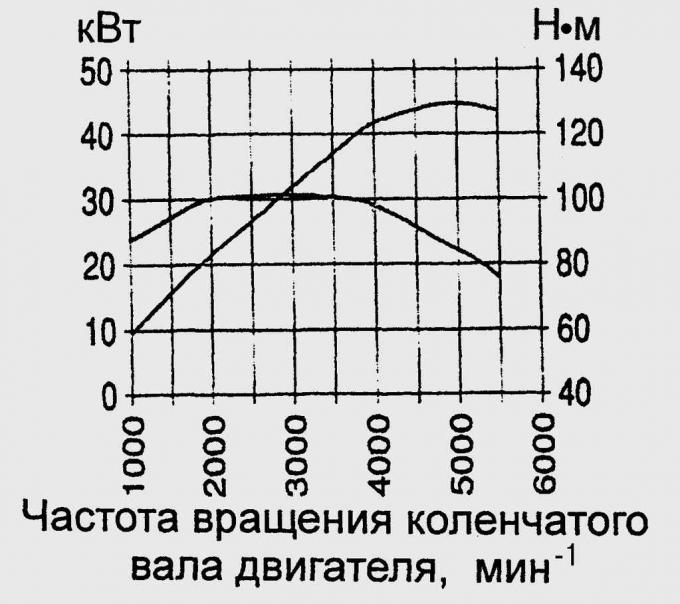
Fig. 4.5. Endura-E engine power diagram, 44 kW (60 hp)
Suction pipe made of plastic
To effectively increase the efficiency, Ford has developed new cylinder heads for Endura-E engines with holes that provide swirl of the fuel-air mixture flow and compact combustion chambers. On the suction side, plastic suction pipes with smooth inner surfaces are installed, which have better thermal insulation. This completely eliminates the jerky movement symptom of the car when running on a lean fuel-air mixture, which was common in older OHV-HCS engines. In this case, the fuel-air mixture passes through the plastic pipe without condensation, and the behavior of the engine during warm starting is also improved due to reduced heat loss.
Sequential fuel injection is standard on Endura-E engines
Further new features on all Endura-E engines include sequential fuel injection, the latest EEC-V engine control unit, a near-engine catalytic converter, a cast aluminum oil pan, and a new engine mount.
Overall, all the changes to the Endura-E engines have resulted in significantly improved engine response and a noticeable reduction in interior noise levels.
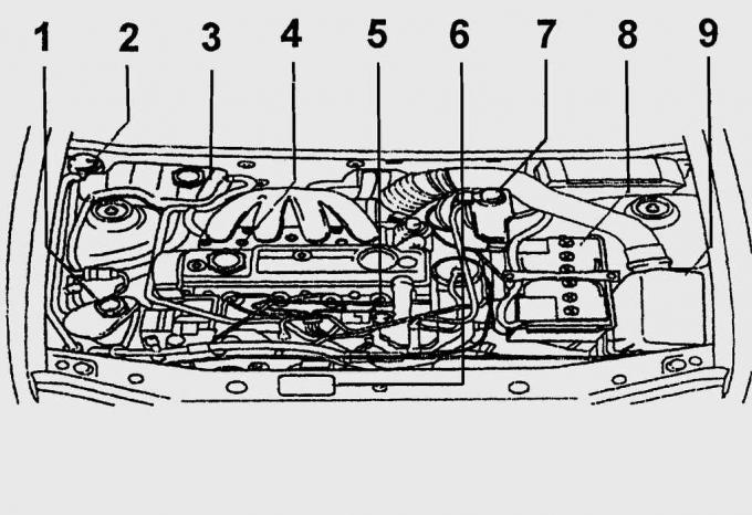
Fig. 4.6. Engine compartment with Endura-DE 1.8 engine: 1 – hydraulic power steering reservoir; 2 – washer reservoir; 3 – expansion tank of the cooling system; 4 – oil filler neck; 5 – Engine oil level indicator; 6 – vehicle data plate; 7 – brake fluid reservoir; 8 – battery; 9 – air filter
1.8 l OHC diesel engine (44 kW/60 hp) with EEC-V electronic control unit and oxidation catalytic converter - standard equipment since 1996
The new Endura-DE engine is a further development of the 1.8 l diesel engine (44 kW/60 hp at 4,800 min⁻¹).
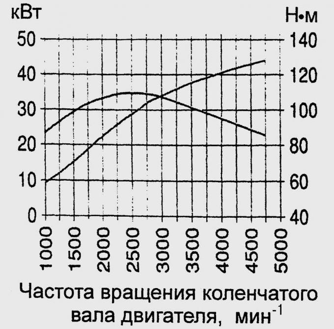
Fig. 4.7. Endura-DE engine power diagram, 44 kW (60 hp)
It is distinguished from all Fiesta engines by its specifically low fuel consumption. Its fundamental component modifications correspond to the displacement of the petrol engines. Specific changes to the Endura-DE engine – it was developed on the basis of the latest EU exhaust gas regulations – are limited to new injection elements, a differently calibrated and controlled EEC-V unit, an injection distributor-pump, and an oxidation catalytic converter located near the engine, the operation of which is controlled by an electronic unit in the Fiesta. Since 1996, cold starting has been improved by glow plugs (EZD 35), which also limit the pre-glow time to 4 s at outside temperatures down to –15°C. The power diagram of the Endura-DE engine is shown in Fig. 4.7.
Technical solutions for reducing noise of the diesel engine of the Fiesta
Modified engine mounts, a free-standing air filter, a new exhaust system and additional noise-reducing measures make the Fiesta diesel engine quieter than its predecessors. The 1753cc Endura-DE engine delivers adequate power in the upper rev range and pulling power in the mid-range. The torque curve of the swirl chamber diesel engine is exceptionally flat – this translates into good pulling power in practice. The Endura-DE engine reaches its peak torque of 105 Nm at 2500 min⁻¹, and almost 70% of this is consistently present above the overall power curve. The diesel engine accelerates the car from 0 to 100 km/h in 17.6 seconds, and at 155 km/h the fuel pump regulator limits the top speed. At typical diesel driving conditions – preferably at low engine speeds – the maximum diesel fuel consumption is 5.7 l.
Choosing the best option for engine repair - in a workshop or on your own
Despite their robust design, Fiesta engines require repair and adjustment work. This work should be performed in a workshop. Qualified mechanics have the necessary specialist knowledge and experience and, as a rule, have the necessary tools to perform most repairs.
For example, an unprofessionally replaced timing belt can cause serious damage to pistons and valves. A qualified repair to replace the cylinder head gasket and valves will save you from at least repairing engine bearing damage. If you are not completely sure that you can repair the engine yourself, forget about doing it yourself in the interests of your wallet. All that is left is a number of inspections and maintenance tasks that you can do yourself.
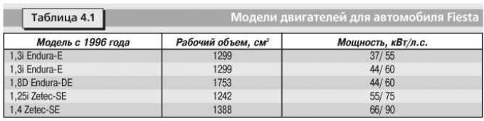
Engine models for Fiesta car
Engine models for the Fiesta are shown in Table 4.1.

TECHNICAL DICTIONARY
Engine components
Cylinder block.
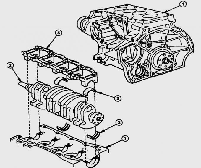
Fig. 4.8. Cylinder block of the Zetec-SE engine of the Fiesta car: 1 – cylinder block; 2 – main bearing shells; 3 – crankshaft with eight counterweights and five main journals; 4 – jumper with caps for main bearings
It contains the crank mechanism and elements of the engine lubrication system. Additional units and components, such as the generator, starter and ignition system, are installed on the periphery of the cylinder block. The cylinder blocks of both Zetec engines are made of a light alloy of aluminum and silicon, and gray cast iron is used in the manufacture of Endura engines. Strong cast side walls and a bridge with caps for the main bearings make the block especially resistant to twisting (Fig. 4.8).
Cylinder head.
In modern engines, the cylinder head is made of a light metal alloy and is mounted on top of the cylinder block. The head has intake and exhaust channels, cooling and lubrication channels, valve seats, valve mechanism bearings, as well as threaded holes for spark plugs or fuel injectors and the combustion chamber. The cylinder head gasket is located between the cylinder block and the head, it protects both parts from oil, coolant and air getting into them from the outside and from the inside.
Cylinders.
In them, the pistons move between the lower dead center "UT" and the upper dead center "OT". The diameters of the working surfaces of the cylinders exactly correspond to the diameters of the pistons, and their surfaces are additionally honed. The cylinders are cooled through cooling channels or, in the case of wet working liners, directly by cooling liquid.
Pistons.
They move in the cylinders and transmit the pressure of combustion products through the connecting rods to the crankshaft. They are made of a particularly light and heat-resistant alloy. Their main elements are the piston bottom, grooves with piston rings, a hole in the boss for the piston pin and a piston skirt. The piston pin connects the piston to the connecting rod. The upper compression piston rings seal the combustion chamber from the crank mechanism. The lower oil scraper ring removes excess oil from the cylinder wall into the oil sump.
Connecting rods.
They connect the pistons to the crankshaft and consist of a hole in the upper head into which the piston pin is pressed, a connecting rod rod, a lower connecting rod head and a lower head cover that covers the crankshaft journal.
Crankshaft.
Together with the connecting rods, it transforms the reciprocating motion of the piston into rotational motion in order to obtain torque. The crankshaft consists of main journals that rotate in the main bearings of the cylinder block, and two counterweights for each cylinder, which are connected by connecting rod journals. The crankshafts of Fiesta engines have five main bearings and four connecting rod bearings offset by 90°. All bearings are equipped with replaceable liners, which are changed in case of their wear.
Valves.
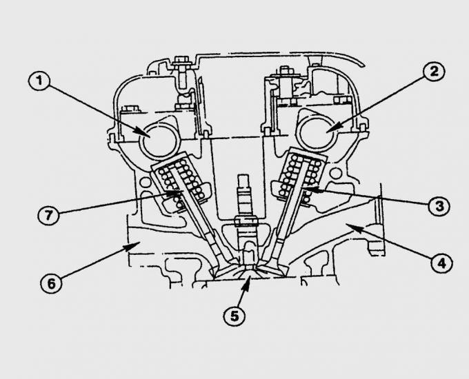
Fig. 4.9. Valve train of OHC/DOHC engines of Fiesta cars, driven by a toothed belt: 1 – exhaust camshaft; 2 – intake camshaft; 3 – inlet valve; 4 – inlet channel; 5 – spherical combustion chamber; 6 – outlet channel; 7 – exhaust valve
Controls the change of strokes in four-stroke engines (intake, compression, combustion, exhaust). In Endura engines, the valves are located in a row in the cylinder head, and in Zetec engines, the valves are located on the side (radial arrangement). The moving parts in the cylinder head form the valve mechanism.
Camshafts.
The valves open and close depending on the engine crankshaft speed and the position of the pistons at precisely set intervals.

TECHNICAL DICTIONARY
The operating principle of a four-stroke engine:
Intake (1st stroke).
The piston moves from top dead center "OT" to bottom dead center "UT". The intake valve opens and the fuel-air mixture is sucked into the cylinder.
Compression (2nd stroke).
The piston moves from the bottom dead center "UT" to the top dead center "OT" and compresses the sucked in fresh fuel-air mixture. The intake and exhaust valves are closed.
Working stroke (3rd stroke).
Before the piston approaches the top dead center, the compressed fresh fuel-air mixture is ignited by a spark formed between the spark plug electrodes. The mixture burns very quickly, and due to the sharp increase in pressure in the combustion chamber, the piston begins to move down to the bottom dead center "UT". As the piston moves in the power stroke, it transfers energy to the crankshaft and converts it into rotational motion.
Release (4th beat).
The inertial mass of the flywheel again moves the piston from the bottom dead center "UT" towards the top dead center "OT". Since the exhaust valve is already open, the exhaust gases exit into the exhaust system. Together, the four strokes form the change of the gas mixture in a four-stroke engine. A diesel engine operates on the same principle. In the intake stroke, it sucks in only clean air, compresses it to a greater extent, so that at the end of the compression stroke, the diesel fuel injected into the cylinder ignites spontaneously from the hot air without an additional spark (ignition spark). The remaining change of the gas mixture is completely identical to a gasoline engine.
Working volume of the cylinder.
This is the distance that the pistons travel in their movement from the bottom dead center "UT" to the top dead center "OT", multiplied by the piston area. The combustion chamber has no effect on the working volume of the cylinder. The working volume of the cylinder and the combustion chamber form the volume of the cylinder.
Compression ratio.
The combustion chamber size does not directly affect the compression ratio. The compression ratio means what the volume of fresh air should be at 100% filling (fully open throttle) in the combustion chamber. In Endura engines, the compression ratio is 9.5:1, in Endura-DE – 21.5:1. The Zetec 1.25i engine operates with a compression ratio of 10:1, and the Zetec 1.4i engine – 10.3:1.
Cranking the engine crankshaft
To perform certain operations, the engine crankshaft must be rotated and set to a certain position. In a four-stroke engine, the piston passes the top dead center twice during four working strokes: the first time when the fuel-air mixture entering the cylinders is ignited, and the second time after the exhaust gases are released with the subsequent intake of the mixture. Usually, during various adjustments, it is necessary to set the piston of the first cylinder to the top dead center in the compression stroke.
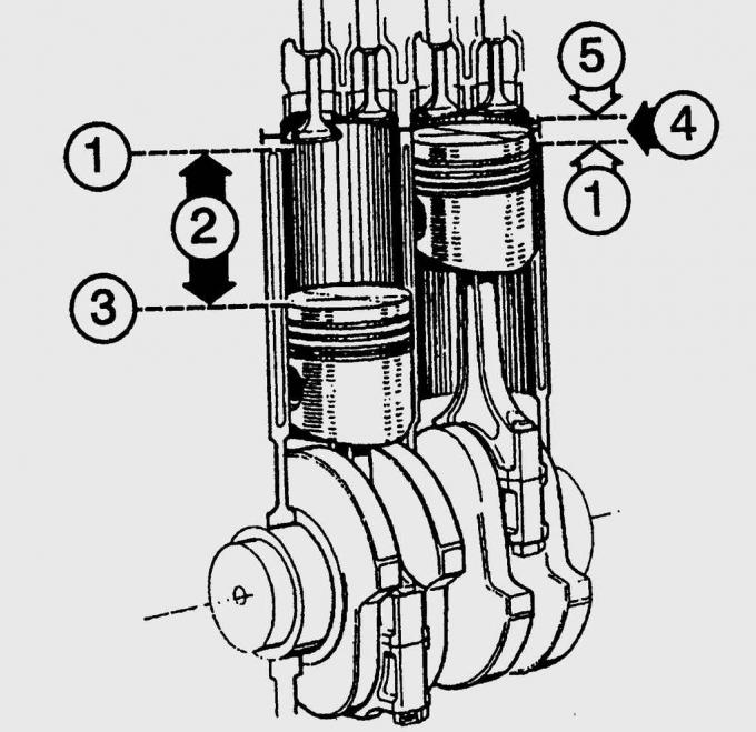
Fig. 4.10. The working volume of the cylinder is the distance (2) that the pistons travel from the top dead center (1) to the bottom dead center (3), multiplied by the area of the piston. The combustion chamber (4) is located in the volume between the piston located at the top dead center "OT" (1) and the concavity of the cylinder head (5)
The piston position at top dead center "FROM" of the first cylinder is shown on the right side in Fig. 4.10. When the piston of the first cylinder (in the direction of travel on the right) is exactly at top dead center, the valves of the fourth cylinder are closed (the exhaust valve closes, the inlet valve begins to open). The valves of the first cylinder are completely closed. In most engines with a distributor ignition, the piston position at top dead center "FROM" of the piston of the first cylinder is determined based on the position of the distributor rotor and the mark on the flywheel, which should be aligned with the fixed pointer.


SEQUENCE OF WORKS
1. Raise the front wheel as if you were changing it and engage 5th gear. When you turn the raised wheel forward, the engine crankshaft will also turn. It will be easier to turn the crankshaft if you first remove the spark plugs. If you do not have the ability to raise and securely support the car, engage 5th gear and gently push the car forward until the piston of the first cylinder is at the top dead center "OFF" position.
2. Without assistance, you can turn the crankshaft using a socket wrench installed on the crankshaft pulley mounting bolt. The crankshaft turns better if you press on the timing belt. When doing this, always make sure that the crankshaft turns only clockwise.
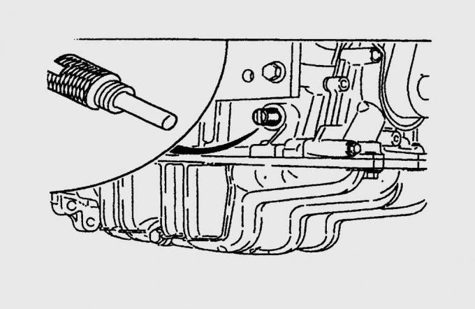
Fig. 4.11. The place where the installation pin (special tool 21-210) is screwed in to set the engine crankshaft to the top dead center position of the piston of the first cylinder
The top dead center "OT" of the crankshaft can only be determined with a special tool. In Ford workshops, a dowel pin "OT" (special tool 21-210) is screwed into the side of the cylinder block for this purpose (Fig. 4.11). The crankshaft is turned until the crankshaft counterweight is pressed tightly against the dowel pin.
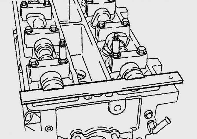
Fig. 4.12. Using a template (special tool 21-162 for Zetec, 21-162-A for Zetec-SE) to set the camshafts to the top dead center position of the piston of the first cylinder
Only a special tool will give you complete confidence in the correct installation of the piston of the first cylinder at the top dead center. Ford technicians install the camshafts in the top dead center position "OT" using a template (special tool 21-162 Zetec, 21-162-A Zetec-SE) (Fig. 4.12).
3. Zetec/Endura-DE engines. If the timing belt tension is loose, the crankshaft must not be turned under any circumstances - this could cause the belt to jump over a tooth without being noticed, the valve timing would be out of sync and, as a result, serious engine damage would occur as a result of the piston bottoms hitting the valves that are not fully closed.

PRACTICAL ADVICE
Checking spark plugs
The ignition system is designed to ignite the fuel-air mixture in each cylinder at a precisely set time. In gasoline engines, this is achieved by an electric spark (electric discharge) created between the electrodes of the spark plug. Previously, spark plugs were very sensitive parts, they had to be replaced after only 12,000 km of vehicle mileage. Modern materials, lead-free fuel, and, above all, the use of high-energy electronic ignition systems have changed the situation dramatically. Although spark plugs are still sensitive to moisture, for example, when washing the engine, their service life has increased to 40,000 km. Ford recommends replacing spark plugs after 45,000 km of mileage. Therefore, constantly monitor the condition of the spark plugs, check their condition every 20,000 km. A specialist can determine the condition of the engine by the appearance of the spark plug. In Endura engines the spark plug gap should be 1.0 mm, in both Zetec versions – 1.3 mm.
[The material was copied from an information website: FordBook.ru]