Shift Lever Assembly
1. Using a small screwdriver, pry the medallion out of the handle button and unscrew the handle button locking screw (see picture).
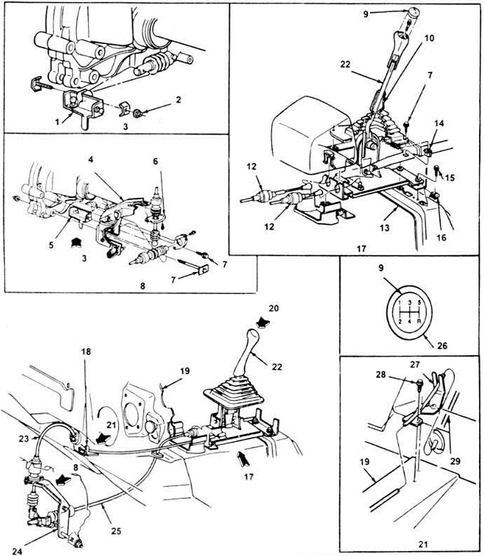
3.1. The layout of the elements of the gear switch.
1. Bracket assembly.
2. Nut.
3. View V.
4. Bracket.
5. Bracket.
6. Plate.
7. Bolt.
8. View W.
9. Medallion.
10. Casing.
11. Bolt.
12. Thrust (cable).
13. Floor panel assembly.
14. "pistons" (4 pieces).
15. Bolt (4 pieces).
16. Clinch nut (4 pieces).
17. View X.
18. Bracket for switch cable (cable).
19. Dashboard.
20. View Y.
21. View Z.
22. Handle and casing.
23. Switch cable.
24. Switch and bracket.
25. Selector cable (cable).
26. Button.
27. Bracket.
28. Bolt (2 pieces).
29. Cable (cable).
2. Additionally, remove the console application, and then unscrew the four screws connecting the ends to the console. Remove the cover and handle from the lever.
3. Remove the console (chapter 11).
4. Unscrew the four bolts securing the switch to the floor panel, wring out the two clamps that hold the switch cable to the control node; using a screwdriver, disconnect the pivoting spheres of the control assembly. Do not bend or damage cables.
5. When installing, lower the ends of the cables into the grooves of the control unit, focusing on the green mark on the lever. Screw on the control assembly mounting bolts and tighten them securely.
6. Insert the cable insulators into the grooves of the lever and secure them with clips. Use a wooden mallet to install the clamps.
7. To snap the lever cable caps onto the ball joints (spherical) supports, use pliers.
8. Install the console.
9. Pull the cover of the shift handle, install the button on the handle, tighten the screws.
10. After screwing the button, put the application in place.
11. Install the console application.
Derailleur Cables and Bracket Assemblies
12. Remove the console handle and cover with the button.
13. Pull the mat off the dashboard so you can access the cables.
14. Remove the pipeline of a heater of back sitting.
15. Loosen the two set screws and remove the cable bracket (see figure 3.1).
16. Loosen the cable grommets, disconnect them from the floor panel and from the instrument panel.
17. Raise the car, install it on racks.
18. From under the vehicle, remove the two stoppers securing the cables to the switch and bracket assembly.
19. Using a screwdriver, remove the cable heads from the clamps of the swivel ball bearings, pull the cable insulators out of the grooves of the brackets.
20. Loosen and unscrew the two mounting bolts and remove the switch and bracket from the gearbox housing.
21. Loosen the nut that secures the clip relative to the inner switch rod, remove the clip.
22. Pull the switch cables out through the passenger compartment and remove them completely.
23. When installing, thread the cables from the passenger compartment. The switch cable goes through the hole in the dashboard, and the selector cable goes through the hole in the tunnel. Make sure that the ends of the cables, together with the closed covers, are pulled through the holes, and the seals "sitting" tightly.
24. Install cable bracket and screws. Tighten the screws firmly, make sure the switch cable is hooked on the hook of the bracket.
25. Install the heater pipe under the rear seat, lay the floor mat in place.
26. Replace the switch lever assembly.
Visitor comments