The diagrams do not indicate the cross-sections or diameters of the wires, nor their digital designations.
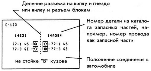
All plug connections (c -), soldered connections (s -) and ground connection of the mass (g -) are additionally presented in the information parts of the diagram. These additional drawings contain information about the location of these places on the body.
The additional drawings indicate the connection number, its type, as well as the number and color of the wires.
Conventional symbols used in the diagrams
 | Powered by or continued on |
 | Symbol indicating special version (e.g. "Australia"). |
 | The connection is not available in all vehicle types. |
 | Shielded connection. |
AKB - battery
off - switch
KL - control lamp
KS - combustion chamber
OZH - coolant
PP - fuse
SVT - fuel injection system
UOZ - ignition advance angle
XX - idle speed
EM - electric motor
Wire color designation
BL - blue
BR - brown
GE - yellow
GR - grey
GN - green
RS - pink
RT - red
SW - black
VI - purple
WS - white
[This publication was borrowed from the website Fordbook.ru]